netTerrain 9.5 End-User Guide

Document Code. GN_D_nT9-01 Last revision: 08/11/2022
© 2022 Graphical Networks LLC. All rights reserved.
Graphical Networks and netTerrain are registered trademarks of Graphical Networks LLC. Other product names mentioned in this manual may be trademarks or registered trademarks of their respective companies and are hereby acknowledged and stuff.
This document was created with 100% recycled electrons.
Before printing, please be mindful of that PC load letter and consider the environment when hitting the printer with a baseball bat.
Image: Matterhorn, Switzerland.
Graphical Networks LLC
Telephone: +1-240-912-6223
Fax: +1-240-912-6339 (We still use these to accept your purchase orders)
1 About this Guide
This document is divided into the following mind-blowing chapters:
-
Chapter 1, “About this guide”.
-
Chapter 2, “Introduction to netTerrain”
-
Chapter 3, “Navigating the system”
-
Chapter 4, “Working with diagrams and objects”
-
Chapter 5, “Advanced features”
-
Chapter 6, “DCIM objects”
-
Chapter 7, “Bulk imports and exports”
-
Chapter 8, “Outside Plant”
-
Chapter 9, “Dashboards”
-
Chapter 10, “Change management”
In the extremely unlikely event that you don’t find this manual mind-blowingly fun to read, some sections provide quick video tutorials to help you ease your way into netTerrain. Look for the video icon and link next to it:

1.1 Who should use it
This guide is for you, oh great keeper of network documentation Zen, also known as the netTerrain end-user!
End users in netTerrain are typically associated with the following roles:
-
Diagram Read-Only: read-only users who can only see diagrams and the information displayed within a diagram but have no access to the object properties window.
-
Read-only users: read-only viewers and consumers of diagrams and data.
-
Annotators: read-only viewers with permission to add and edit annotations of their own.
-
Updater: users who can update properties for objects but cannot add new objects or remove objects from a diagram.
-
Editors: network administrators, IT documentation personnel or any other individual tasked with entering and editing data in netTerrain.
1.2 Assumptions
This guide assumes that users have basic knowledge of browser navigation and general computer and networking knowledge. Let’s just say that if we are talking about mouse-clicks and you don’t picture rats running around the kitchen, that’s a start.
2 Introduction to netTerrain
2.1 netTerrain in a nutshell

2.1.1 Description of the problem
IT inventory information is typically maintained in unconnected files and other data sources scattered around the enterprise, such as spreadsheets, legacy databases, service Desk, network and asset management systems, even notes or plain employee knowledge.
Lack of a usable, centralized repository of asset information has a devastating effect on the bottom line:
-
Difficulty in troubleshooting leading to excessive MTTR
-
Provisioning decisions and implementation take too long
-
Assets are scattered and unaccounted for, resulting in unnecessary purchases
-
Zombie servers and cables abound
-
Space and environmental variables are not optimized
-
And much more...
In short, total cost of ownership soars because you can’t manage a system you don’t understand!
2.1.2 The netTerrain solution
netTerrain is a multi-user IT visualization solution used in many different scenarios:
- Network inventory and documentation
- Inside and outside plant documentation
- Data center infrastructure management (DCIM)
- Cable management
- Outside plant fiber, copper and wireless documentation
It enables organizations to automate and simplify the management and visualization of IT components, links and their relationships within networks and data centers.
netTerrain comes in three flavors: netTerrain Logical, netTerrain DCIM and netTerrain Outside Plant. We refer to these as products, although technically netTerrain is just one product with the base one being netTerrain Logical and it can be extended to DCIM by adding reporting, work orders and the capability of documenting smart devices and racks and netTerrain OSP by adding dynamic map, strand and circuit management support. This guide will cover all three products.
netTerrain Logical lets users create any type of IT or non-IT views, modeling each object in detailed fashion, using custom properties and hierarchies.
netTerrain DCIM is a Data Center Infrastructure Management solution that can track assets, document racks, devices and cables and monitor and report on the state of the Data Center. All three solutions offer discovery and integration options as well (covered in the Integration Toolkit Guide).
netTerrain OSP is an outside plant solution that helps in documenting the campus fiber, copper and wireless networks traversing geographically dispersed areas laid out on GIS maps.
The netTerrain catalog includes many predefined vendor specific configuration items. Users no longer must worry about how many ports a router has, or what icon must be used on a network diagram since netTerrain manages such things as vendor specific images or subcomponents automatically. These subcomponents are also automatically generated in the netTerrain visualization.
2.1.3 Key features and visualization
2.1.3.1 Network documentation
netTerrain is a full-fledged IT inventory management and network documentation system with advanced automation features.
netTerrain can produce topology views for assets such as network devices, servers and power devices. Users can create any type of network with a few clicks. This is a useful feature for network managers. Once networks are created in netTerrain and devices mapped to them, users can:
-
Track all necessary device and link attributes by users, technology, protocol or any other attribute
-
Get real-time statistics for network topologies and its components
-
View networks by type and change icons, colors, link thickness or any other visual cue by any attribute value
-
Using the Integration Toolkit users can discover the network using SNMP and other protocols or from third-party systems and view real-time alarms on netTerrain diagrams
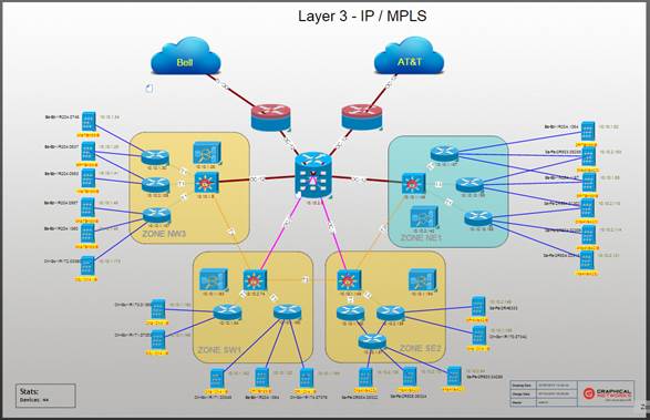
Layer 3 network view example
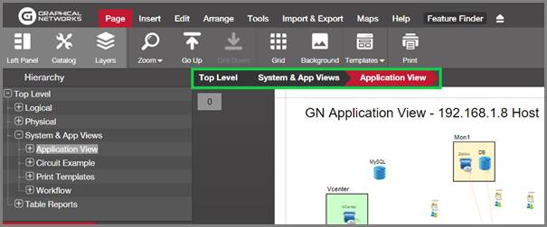
2.1.3.2 Application, system and miscellaneous views
With netTerrain users can create a myriad of diagram types that represent different aspects of the organization. Thanks to a fully flexible catalog of nodes and links, users can create topology, system and application views displaying a variety of IT and non-IT objects.
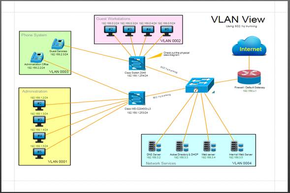
Application View example
2.1.3.3 Data Center Infrastructure Management (DCIM)
Along with regular node and link types that can model any type of entity, netTerrain includes smart devices, cards, ports and racks. These so-called smart objects have built-in business rules geared towards the documentation and inventory of your data center, such as rack occupancy, power and weight tracking, slot availability, port connectivity, DCIM reporting and much more. netTerrain DCIM includes a sophisticated network, infrastructure and environmental monitoring module that is outside the scope of this guide.
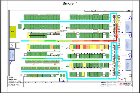
Floor plan view example
2.1.3.4 Link (cable and circuit) management
Links in netTerrain support an unlimited number of custom fields and can store any type of attribute (list fields). Using visual overrides, links can dynamically change their color, thickness and style if a certain value matches a user predefined rule.
netTerrain includes a rules engine to specify which link types can be connected to which node types, if a cable needs to have matching port connectors and much more.
netTerrain also has the ability create Circuit Layout Records (CLRs) to see end-to-end connectivity as well as multiple tools to create multi-connections at once.
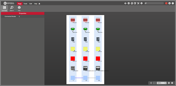
CLR view
2.1.3.5 Outside Plant (OSP)
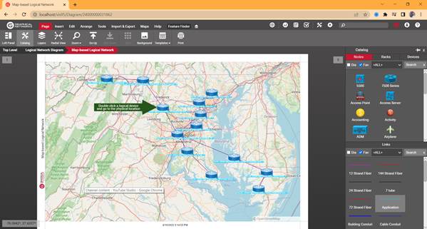
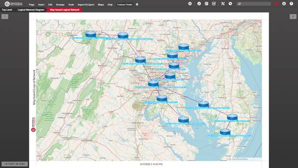
With netTerrain OSP you can visually manage your copper, fiber, wireless or transmission networks and GIS based outside plant views.
You can use fully GIS-enabled maps, manage any type of outside plant element and combine them with inside plant cable and asset management.
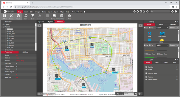
Outside plant dynamic map view
2.1.3.6 Dashboards and reports
netTerrain includes a full-fledged business intelligence engine for the creation of slick reports and dashboards. These reports are accessed from any part of the project and display different dashboard tabs that can be discriminated based on default role access.
netTerrain ships with a series of built-in reports such as dashboards for Data Center summary views, device aggregate reports, connectivity reports, admin reports and much more.
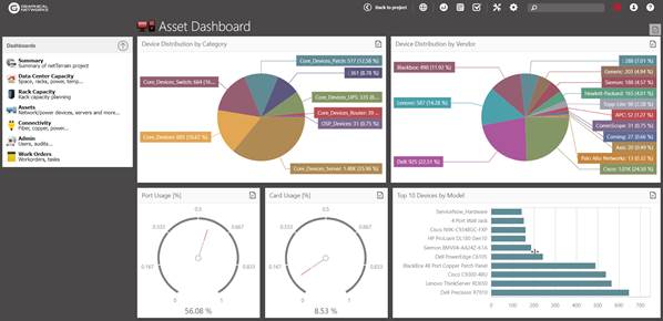
Dashboard view
2.1.3.7 Import mechanisms
netTerrain provides several bulk import methods, including Microsoft Excel, Visio and netViz import buttons as well the Collector and Integration Toolkit (ITK) to capture data from the network or other systems and other third-party or homegrown repositories.
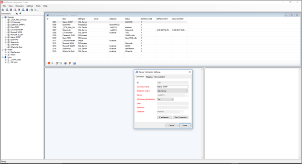
Integration Toolkit
2.1.3.8 Security
netTerrain has a security model based on 8 roles: These roles comprise the following permission levels, and each one inherits the permission level from the previous one:
1) No access: users are prevented from accessing certain parts of the project.
2) Diagram read only: users may view data that is displayed within a diagram but can’t view the data fields associated with objects.
3) Read-only: users may view data and diagrams, but lack the permission levels to modify, add or remove data from the database or diagrams.
4) Annotator: users can add, edit and delete their own comments and palette objects.
5) Updater: users can edit data fields for objects but cannot add or delete existing objects in a diagram.
6) Editor: these are the users that can add, edit and remove IT related records from the database. They can also modify diagrams.
7) Power-User (or catalog managers): In addition to data-entry functionality, power users can also manage the catalog and lookup tables.
8) Admin: administrators have full access to the system via the web browser and can create new users and groups as well as run the audit trail reports and change settings.
netTerrain supports Active Directory (AD) so that groups defined in AD can be synchronized with groups in netTerrain.
2.2 System organization and architecture
Below is a view of the system, as understood from the user’s perspective. This view aims to show the typical data flow into and out of the netTerrain database, which serves as the de-facto information repository.
The following functional view shows the data flow in netTerrain:
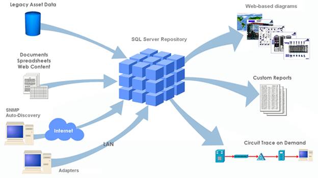
Functional view
Bulk imports and legacy asset data are typically imported during initial deployment or for field personnel with no access to the system, and ‘steady state’ daily asset tracking is accomplished by means of the data entry process using the netTerrain browser or automatically through the netTerrain Integration Toolkit and Collector.
The diagram below shows the architecture of netTerrain, with each component and how it interacts with the system:
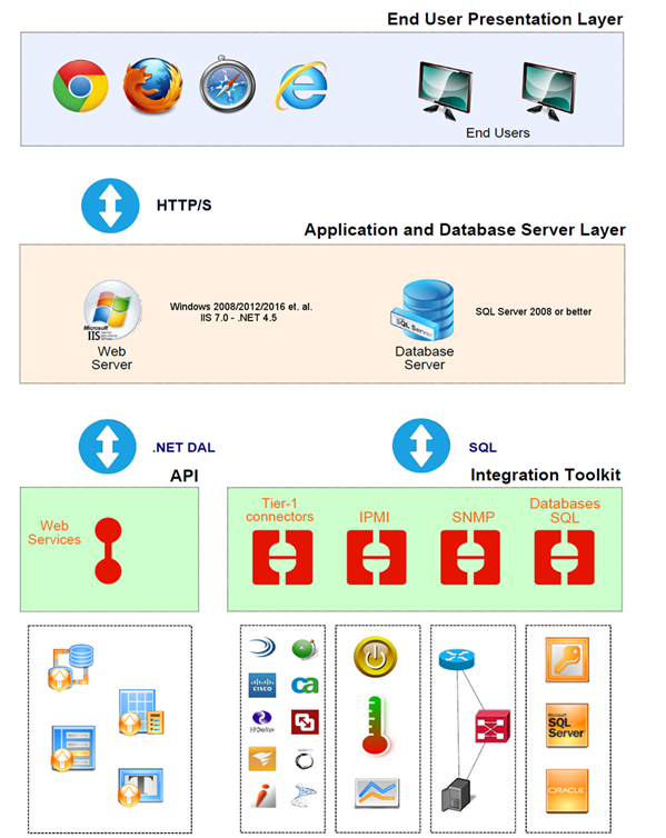
netTerrain architecture diagram
2.3 What’s new in 9.5
 What's New in 9.5
Welcome to netTerrain 9.5, our third release in the 9.x series (also called “Europe”, as you may see from the new pretty guide covers featuring beautiful landscapes from the continent, as well as the login pictures).
In this new minor release, we continued our focus on usability, performance and design improvements. There are also several bigger features and the usual small fixes and improvements. Below is a bulleted list of some of the bigger items that you may care about, if you are a current 9.1 user:
2.3.1 Improved diagram loading times
80,000 lines of code were refactored in this release. That’s right. We underwent some serious refactoring on the server-side and on average this resulted in a 30% improvement of diagram loading times, by far the most important performance metric from a user’s perspective. Just to be clear: this is an average loading time improvement. Certain types of diagrams, depending on number and mix of objects may load twice as fast, others may not have changed much at all.
The biggest improvement we have seen is probably in the OSP diagrams. Some of the diagrams we have tested have seen a drop of loading times of over 70%, but again, this depends on so many factors that it is hard to predict for a given diagram how much faster it is until it is tested.
2.3.2 Event console
With 9.5 we added a whole new monitoring tool, which is the netTerrain event console. The event console can be accessed from anywhere in netTerrain and provides users with real-time alarms, events, traps and notifications in table format.
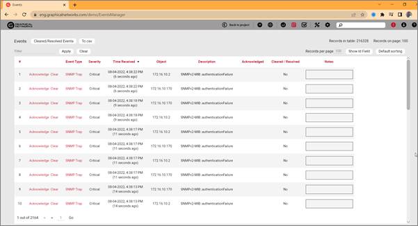
The console also provides some basic tool for filtering events, exporting data, acknowledging and clearing events and more.
Visual overrides can also be configured to trigger events and populate the events table. When a new event happens, the events icon shows up in red, indicating that a new record is available and requires the user’s attention.
2.3.3 Google maps and ESRI maps support
A huge improvement in our OSP offering includes the support for Google maps and ESRI. Google maps support includes the standard map views as well as satellite views. These new map sources are configured in the settings.xml file and by default, we provided Google standard and satellite views as out-of-the-box options.
Just like with OSM featuring a few different views, you can switch to a Google maps for any given diagram by simply right-clicking on the diagram and choosing the source.

Additional OSP sources
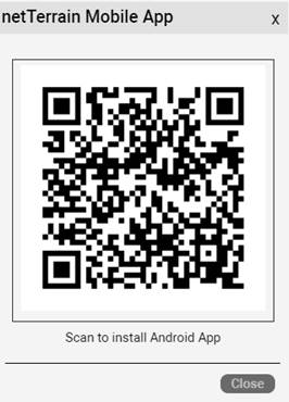
2.3.4 New QR code for easy mobile app download, and new rack audit capability for mobile app
This one is pretty slick and pertains the mobile app. First off, you can now easily download the mobile app from netTerrain by scanning a QR code from the mobile app menu in netTerrain.
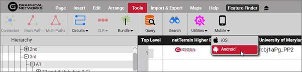
Once you pick your preferred and vastly superior phone OS, you can then proceed to scan the QR code with your phone, which will take you to the app store to download the app.
In addition, the app itself now can be used to audit racks. with the netTerrain app scanner feature you first scan a rack and then verify the inventory status of devices mounted on that rack, in addition to all the other slick features it already has.
2.3.5 Redesigned tables
In our continuous attempt to improve the look and feel of netTerrain we decided to give all the tables in netTerrain a fresh design. These design changes affect all types of tables, such as table views, search results, admin and catalog tables and more.
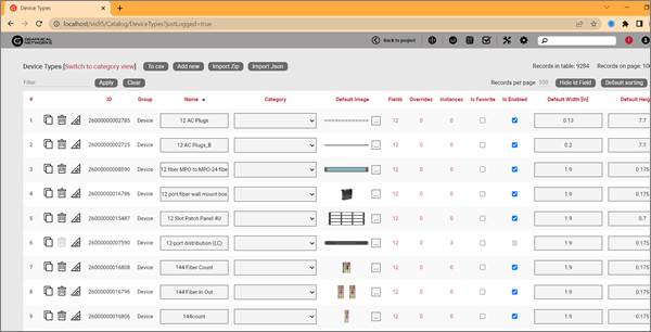
New table design
The new table designs are more consistent in how the standardized color patterns are implemented, improved icons, better distribution of UI elements and overall better readability.
2.3.6 Other features
There are numerous other features in this version, including the following (partial) list:
- Import/export catalog node types to Json
- Ability to preview Excel imports
- Improved VLAN reports on ports and devices showing VLANs directly on properties or as displayed field
- Ability to generate CLRs for single strand paths
- New feature to interface with Chatsworth's rack locking system
- Map halos can now be disabled for a diagram from the Miscellaneous tab in Layers
- Easier license upgrade mechanism with bin files
- New button to add default custom device, card and rack fields to all existing types
- Ability to connect cable card to card
- New option to show password during login
- New report for rack utilization and power available from custom context menus
- New notes column for tasks in work orders
- New custom dll to launch a report by name from the custom context menu
For a full list of improvements, please refer to the 9.5 release notes, which are available for any current customers under maintenance. For a list of feature improvements related to version 9.1 or older you may have to dig up the corresponding newsletters and release notes provided on our website or just ask us.
Attention!
This section describes changes that affect any one of our netTerrain licenses.
Some features may only apply to users with a netTerrain DCIM or netTerrain OSP license.
This section only describes improvements since version 9.1.859.4960.
2.4 Help and support
There are several ways to get support for your netTerrain tool. As you might expect, support is only available for customers with a valid maintenance contract.
2.4.1 Live support
Live support is available through the following channels:
-
Customer support portal (preferred method): https://graphicalnetworks.zendesk.com/hc/en-us/.
-
You need your customer portal user and password, if you don’t have one, you can request it at support@graphicalnetworks.com
- Live chat (not always available): live chat link on our website (www.graphicalnetworks.com)
- Phone support: 1-240-912-6223
2.4.2 Getting help from your netTerrain tool
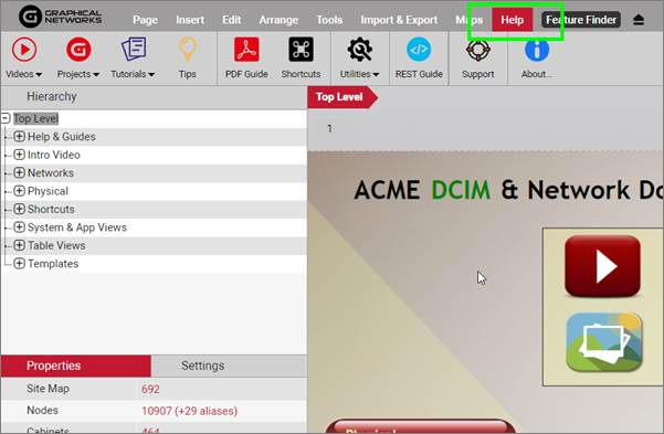
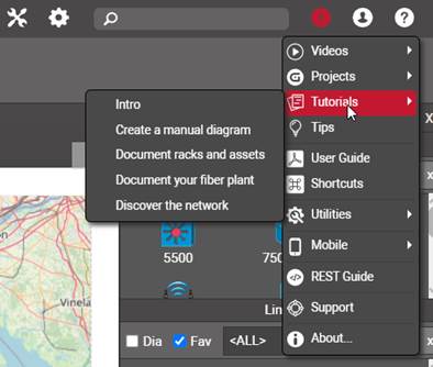
You can also get help straight from your netTerrain software by clicking on the help menu. The help menu can be accessed from the main help bar, as well as from the top right corner.

Help menu in netTerrain
The help menu includes:
- Videos to help you get started
- Sample projects online
- The “dragonfly” tutorial that can be relaunched as many times as you want
- Animated gifs on how to get started and carry on with basic tasks
- PDF guides
- The shortcut (hotkey) list in PDF format
- The REST API guide
- Customer portal support link
- About dialog
It is important to note that the PDF guides are context specific. If you are in the “project” (end-user part of netTerrain) you will see the end-user PDF guide. If you navigate to the catalog, the help menu provides the catalog guide. If you are an administrator and you navigate to the admin console, you see whole set of extra guides not available for regular end-users.
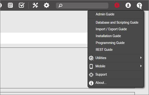
Help menu in the admin console
These extra guides only available from the admin console include:
- Programming guide: this is the SOAP API guide
- Database and Scripting guide: this provides information about the database structure and how to write scripts against it
- Import/Export guide: this guide explains how to set up the import/export mechanisms on the client and/or server and how to use them
- Installation guide
- REST Guide: this is the REST API interface link, which opens swagger
3 Navigating the system
netTerrain is at its core a collection of diagrams of your data center, fiber plant or network topologies. You can create any number of user-friendly pictorial representations of your IT landscape, such as physical, logical and application views. In addition, as we briefly showed in the previous chapter, netTerrain also displays table views, dashboards and reports.
End users of the system require no special software to navigate netTerrain diagrams. By simply opening a browser and accessing the login page, a viewer can start navigating the diagrams depicted in netTerrain.
3.1 User level permissions
Before we dive into diagram navigation features, we will review the netTerrain user permission structure. This is important since not all buttons and menus are visible to all users. Depending on the permission level, some options can be enabled, disabled or not visible at all.
netTerrain has a security model based on 8 roles:
1) No access: this role is mostly used to ‘park’ users that may not have access to the project but should not be deleted from the database. This role can also be assigned on a per diagram basis, so that users may have no access to certain parts of the project.
2) Diagram Read-Only: users may view data and diagrams, but lack the permission levels to modify, add or remove data from the database or diagrams. Users will not be able to view the object properties or settings.
3) Read-only: users may view data and diagrams, as well as the property values associated with objects, but lack the permission levels to modify, add or remove data from the database or diagrams.
4) Annotator: users can add, edit and delete their own comments and palette objects. The rest of the data can only be accessed in read-only mode.
5) Updater: users can modify object properties but cannot add new objects, move them on a diagram or delete them from the database.
6) Editor: users that have full permission to make any modifications in the project, including any so-called “CRUD” operations (create, read, update, delete).
7) Power-User (or catalog managers): in addition to data-entry functionality in the project, power users can manage the catalog.
8) Admin: these users have the highest permission level and full access to the system. They can create new users and groups as well as run the audit trail reports and change global settings.
3.2 Logging in
To access the netTerrain web interface, the user needs the URL that points to the web server, usually something like http://<server>/<virtualDirectory>, where <virtualDirectory> is the name of the web server directory assigned to netTerrain.
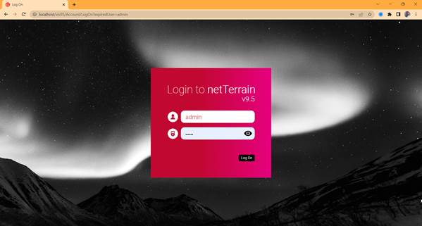
Login dialog
Users can click on the show password button. Also note that your system admin may set up login to work with Active Directory or Azure AD, so the screen may very a bit.
To log off the system, simply click on the Log Off link (top right corner). All session data will be cleared after you logged off. To view or edit a specific diagram the user needs to log back in.
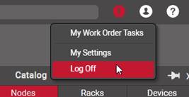
Logging off
If you provide incorrect netTerrain (or AD) credentials, netTerrain will throw an error. Other log in errors are possible if your server is not correctly configured (see netTerrain Admin Guide).
Attention!
If you get an error like the one depicted below, the application server is not properly connecting to the database. Consult with your system administrator to trouble shoot the problem (also see the Installation Guide).
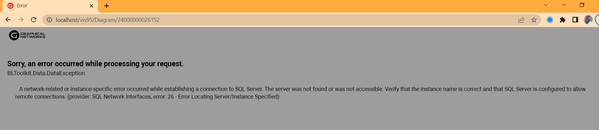
Application connectivity problem
As mentioned above, the login process can be integrated with Active Directory, in which case the user may choose to enter the windows credentials or use a native netTerrain login (if it exists). If the ‘Support Active Directory accounts’ checkbox is checked in the admin console (see Installation Guide or Admin Guide for Active Directory settings), no credentials need to be specified for logging into netTerrain.
If two-factor authentication is enabled, then the user needs to also provide a Google 6-digit code from the Google authenticator app on their phones.
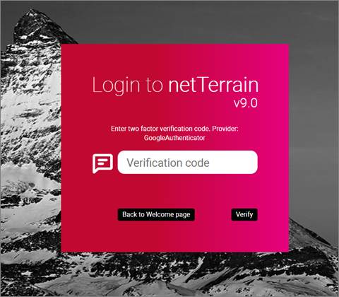
Two-factor authentication code verification dialog
3.2.1 Animated tutorials for beginners
For novice users netTerrain now starts up with an animated tutorial to show you how to get started with the tool. This tutorial teaches you the very basics: how to add a node, how to double click and add some links. It only launches automatically when a newly created user logs in for the first time.
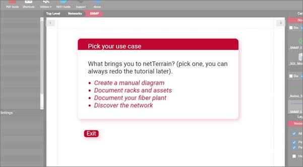
Animated tutorial
The novice user will be prompted to perform basic tasks assigned by our friendly dragonfly, while being shown around.
3.2.2 Bypassing the login
netTerrain does have a feature to bypass the login process and provide a read-only mode interface of netTerrain (see Installation Guide). When netTerrain is set up to ‘Bypass login mode’ any valid netTerrain URL that is entered in your browser (or clicked on), will render a netTerrain diagram without the need to authenticate against the server.
This is useful in cases where you want to see a netTerrain diagram inside another web application for example.
As mentioned above, in such cases you will be navigating diagrams in read-only mode. You can, however, login after the fact, by clicking on the ‘logon’ link on the upper right corner of the page, as depicted below.
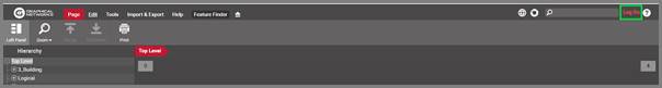
Logging into netTerrain during a bypass login session
3.2.3 Seeing who’s online
Once you logged in, you can see if there are other users currently only and where, by hovering over the online indicator on the top left corner of the diagram.
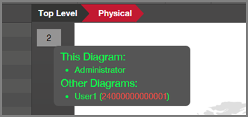
Seeing who’s online
When another user is on the same diagram, the indicator has a pink fill color, if everybody else is on a different diagram the indicator is grey. You can access the diagrams that other users are currently navigating by simply clicking on the diagramId link.
3.2.4 Structure of netTerrain URLs
netTerrain diagrams all use “deterministic URLs”, with a regular structure, or pattern:
The diagramId is the unique id assigned by netTerrain to any node that can contain a diagram. An example of the top-level diagram is the following:
Attention!
Just like with any other web application, an incorrect URL will redirect you to an error page (or 404 page). Some of the reasons why you are reaching a 404 page may be the following:
- You provided an incorrect URL (maybe a typo? lack of coffee?)
- a redirect to a diagram that no longer exists
- An incorrectly constructed URL in a custom report or hyperlinked field

Oh noes! A 404!!
3.3 Getting started with diagrams
Once logged into the system for the first time, users find themselves in the so called ‘project’ side, where they can start navigating the different diagrams that comprise a netTerrain project. After a period of inactivity (15 minutes by default), the user will be logged off the system.
The inactivity period can be modified in the netTerrain application by editing the web.config file (see Installation Guide).
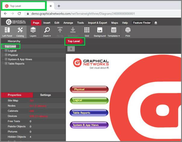
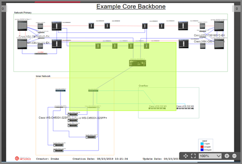
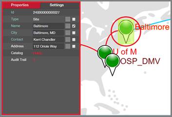
Sample Top Level diagram, with indicators
To drill down into other levels of the project, simply double-click on a node or click on any leaf on the hierarchy browser, as depicted in the image below.
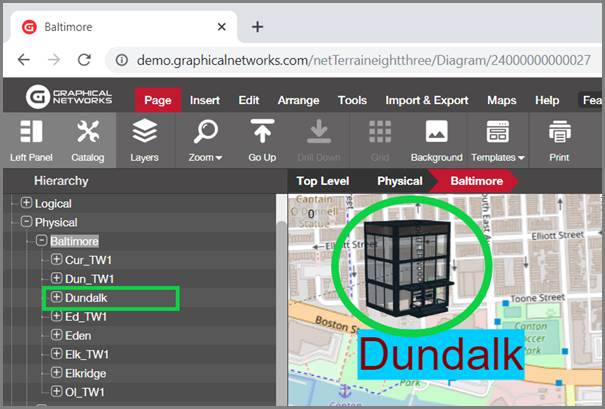
Accessing a sub diagram by double-clicking or selecting a leaf object
Besides the project, netTerrain also contains a catalog, a reporting dashboard, a work order section and an administrative console. We will review the different parts of the GUI later but note that not all parts are accessible by everyone. For example, the catalog, which is the placeholder for all the types and metadata that are used in the project, can only be accessed by power users or administrators.
Attention!
The administrative console is the gateway for managing users, groups, global settings and audit trails. This can only be accessed by users with Admin role privileges.
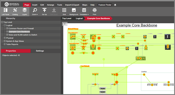
3.4 The netTerrain GUI
The netTerrain graphical user interface (GUI) is designed to simplify the process of managing your diagrams and information. In this section we simply walk you through these elements, and later throughout the guide (as we will regurgitate repeatedly) you can dive deeper into each feature.
Below we review the different parts that comprise the netTerrain user interface, which include:
A) Diagram
B) Menus & ribbons
C) Feature finder
D) Quick access bar
E) Zoom & panning
F) Hierarchy browser
G) Search dialog
H) Properties and settings tabs
I) Catalog
J) Layers
K) Breadcrumbs
L) Notifications, user and help menus
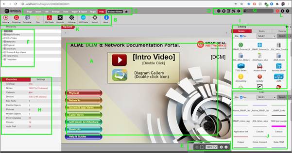
Basic netTerrain GUI components
3.4.1 Diagram
Diagrams in netTerrain are the main actors, and hard to miss: it’s where you place all your objects. There are tons of interesting things that you can do with diagrams, such as adding nodes, links, text, images, palette objects, maps, backgrounds a grid and more.
Every node in netTerrain is also a diagram. You access the node diagram simply by double clicking on it.
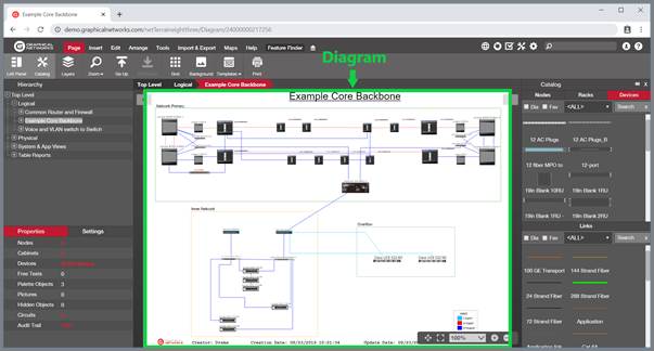
netTerrain diagram, right there in the thick of things!
3.4.1.1 Help notifications
As a new user to the system (and if the sys admin enabled them), netTerrain will provide some basic help notifications when you perform certain actions.
For example, if you click on the zoom in button, a notification prompting you to try out a zoom shortcut will appear.
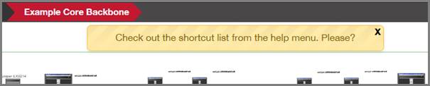
An example notification
Notifications will only show up a few times per action until they stop appearing. However, if you find them annoying (or you are a master ninja netTerrain user) you can disable a notification for a specific action or just disable them all, by simply clicking on the ‘x’ after a notification appears, and then disabling them as shown below:
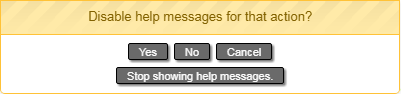
Dialog to disable notifications
3.4.2 Menus and ribbons
The top of the netTerrain project page contains an array of menus, as you may recall from other desktop or web applications.
Starting in version 7.1, netTerrain now provides menus in the form of a so-called “ribbon” (or ribbons).
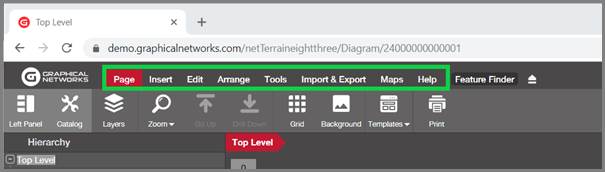
netTerrain menu bar showing the page ribbon
The ribbon is not a new concept; we “borrowed” it and modified it from other well-known tools. Each menu now expands into a ribbon with buttons, where each button has a simple subtext and a detailed tooltip explaining what the button does. You can collapse the ribbon using our ribbon arrow displayed in the screenshot below.
Page menu, ribbon, button and tooltip description
Buttons are context specific, meaning that depending on where and who you are, certain buttons may not be enabled or even displayed.
Note that some of the buttons include submenus, which in turn contain other buttons or icons.
Example of an expandable menu with submenu buttons
Below we will go over each menu and its corresponding buttons.
Tip:
Many buttons can be activated with a keyboard ‘hotkey’ or a combination of keyboard actions. When you hover the mouse over a button, you can see the description of that button and whenever applicable, the hotkey shortcut will be displayed between brackets.
3.4.2.1 Page menu
The page menu deals with operations that affect your overall diagram and page settings.
3.4.2.1.1 Toggle left panel
The toggle left panel hides or displays the hierarchy browser and the properties window. Most users leave this untouched for regular navigation, since you want to see the hierarchy browser and the properties window when you click on an object.
However, in some cases this button comes in handy to provide a full screen view of just the diagram or printing purposes.
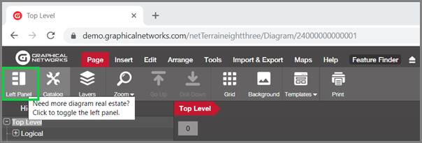
Toggle left panel button
By default, the left panel is displayed. This setting applies to the entire project and is user and session dependent.
netTerrain view, with left panel hidden
Below we will see how you can also hide the panels on the right side and provide a complete full screen view for your diagram.
3.4.2.1.2 Catalog and Layers
Next to the Left Panel button you can find two more buttons that also hide or show dialogs. This time, it’s the dialogs that you may see on the right side. We will learn more about the catalog and layers later, but in short, the catalog and layers panes come in handy for easy drag and drop of objects onto the page and quick filtering of nodes, links or fields.
Now if you want to hide them, that’s what the two buttons displayed below do. For a quick operation you can use the hotkey! F3 (a nod to our netViz users) will operate on the catalog dialog and F4 on the layers.
Notice that the catalog button is not available for updater users (or lower), since they cannot drag and drop objects onto a diagram.
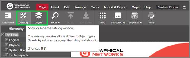
Catalog and layer display button
When the catalog and layer panes are docked they are stacked on top of each other on the right side of the page, as shown below:
Now that we know how to hide all dialogs on the page (left panel, catalog and layers), here is a nice trick, if you want to see a full-page view of a netTerrain diagram:
a) Hide the catalog and layers (use F3 and F4)
b) Hide the left panel and the ribbon! (using the ribbon arrow)
c) Hit F11 for a full browser view and ta-da!
Full screen view using toggle left panel and F11
3.4.2.1.3 Zoom
Zooming is very easy in netTerrain, so much so, that we don’t recommend using these buttons as there are other easier ways of doing that, which we will review later. However, mostly for consistency and compatibility purposes we still have several zoom related buttons available from the page menu.
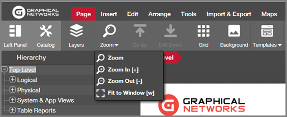
Zoom options
3.4.2.1.4 Go up
By pressing on the ‘Go up’ button, users can go up one level in the diagram hierarchy. Note that by going up, the icon that represents the parent object of the previous sub diagram has an indicator (a surrounding red box by default) showing the container object the user came from. The indicator will blink a certain number of times before disappearing. An administrator can configure how many times the blinking should occur. The type of indicator can also be changed by an administrator.
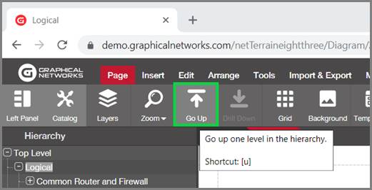
Go up button
Tip:
Use the ‘u’ hotkey for this button! You will get very used to this convenient shortcut for going up.
Attention!
If the ‘u’ hotkey seems not to react is because maybe you do not have the focus on the diagram. Click anywhere on the diagram and you will gain focus back. Also consider that the ‘Go up’ function does nothing when you are at the top level.
3.4.2.1.5 Drill Down
The drill-down function lets users drill into a specific node, which we normally refer to as its sub diagram.
Now you may know that this is also possible by simply double-clicking on the node itself, in which case you are wondering why this button even exists. For starters, some users may not initially know about the convenient double-click option, but even after you were enlightened about this, you may still use the button in case the node double-click function was overridden. In other words: sometimes double-clicking on a node does not take you into the node sub diagram.
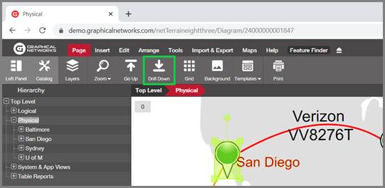
Drill down button to access a node sub diagram
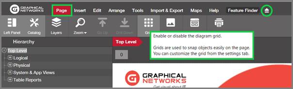
3.4.2.1.6 Grid
As the name suggests, this button enables the grid on a page. To hide or show the grid on a page simply, click on the button. We will review more details about grid settings later.
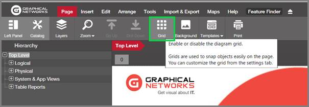
Grid button
3.4.2.1.7 Backgrounds
To upload a background image simply click on the upload background button and select an image file from any local or network drive. As the tooltip explains, backgrounds can be used to set up static images on the background of your diagram, such as floor plans, pictures, static maps and more.
The entire process is reviewed in more detail later, including how to clear a background and image format options.
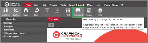
Upload background button
3.4.2.1.8 Templates
In some cases, users may want to apply a standard layout to several diagrams without having to create the objects that comprise each diagram manually every time. To do that, users can set up any given network diagram as a template and then apply that template to any other network diagram. We will review this in more detail later, but for now, know that starting in version 7.1, template buttons are available through the menu as well.
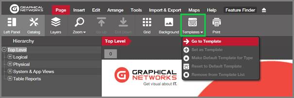
Diagram template options
3.4.2.1.9 Printing
This one should be a bit obvious, we hope. The print button opens a dialog for printing the current diagram.
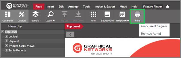
Print button
The netTerrain print dialog provides the user with a few options to send the diagram to the printer. These options include the orientation mode and page size. Since every netTerrain diagram has its own page size, usually you would match up that size with the printer page size, but this is not mandatory. In some cases, you need a large page size in netTerrain to accommodate many nodes without messing with their default sizes, yet you still want to send that diagram to a letter-sized printer page.
The page size options include many standard European and American page sizes but notice that you can also select your own custom sizes.
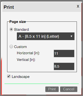
Print dialog options
Attention!
Once you click on the print button on the netTerrain print dialog you can also set printer-specific page, orientation and other settings, which are outside of the netTerrain domain. These settings will really depend on the printer driver.
In some cases, it may be necessary to explicitly match up the printer specific settings with the netTerrain print settings. The screenshot below shows the printer settings for a PDF printer driver. Notice how the orientation and the page size may be selected and even differ from the netTerrain print settings. For optimal resolution we recommend trying different dpi size and page sizes, since raster-based objects may be very pixelated for low resolution outputs.
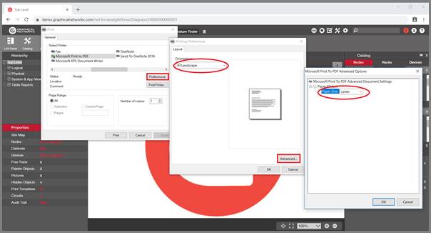
Example of a PDF printer and its settings
3.4.2.1.9.1 Removing headers and footers from the print outs
Sometimes a printout shows headers and footers that are not part of the original netTerrain diagram.
Also, some printouts introduce an extra room for margins, which are at odds with the preexisting margins in netTerrain and add extra blank real estate to your printed diagram.
These are elements introduced by the printer driver and the process of removing them will depend on what browser or printer you are using. Typically, the browser has a page setup option, which you can customize. The screenshot below shows the Firefox page setup dialog, with header and footer options. Notice how the margins are set to zero and the headers and footers are set to “blank”.
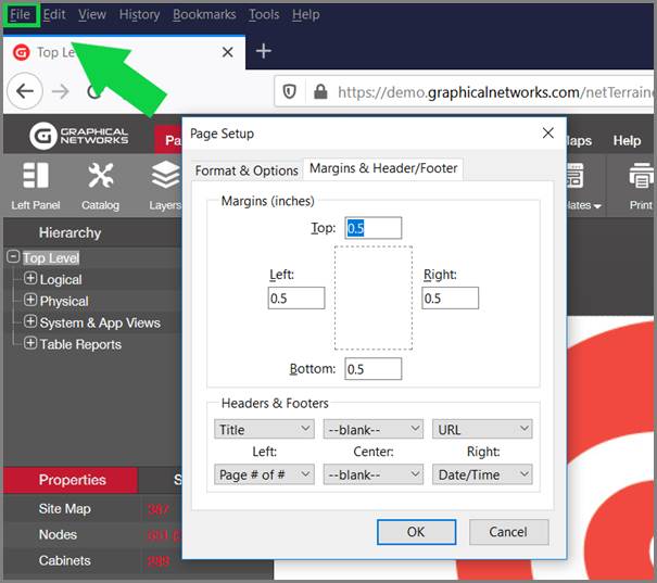
Browser page setup dialog
3.4.2.2 Insert menu
The insert menu provides functions to add and remove nodes, links and other objects in netTerrain.
Attention!
Most of the insert menu buttons are only available to users with editing rights. Users with annotator rights will be able to user the text and palette object menus, but not the menus for inserting actual inventory items such as nodes, devices or racks.
3.4.2.2.1 Inserting nodes, links, devices and racks
We will be reviewing in more detail the different mechanisms for inserting your inventory items, such as nodes, links, devices and racks, but suffice it to say that netTerrain provides several different ways for doing this, including selecting the items from the ribbon drop down menus, as depicted below.
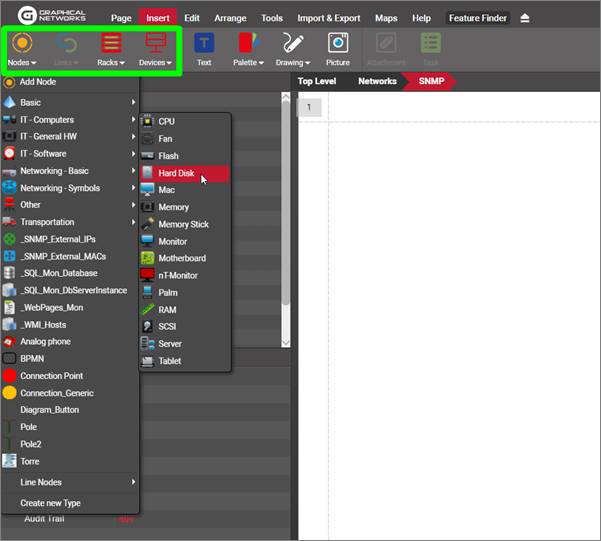
Different insert menu options
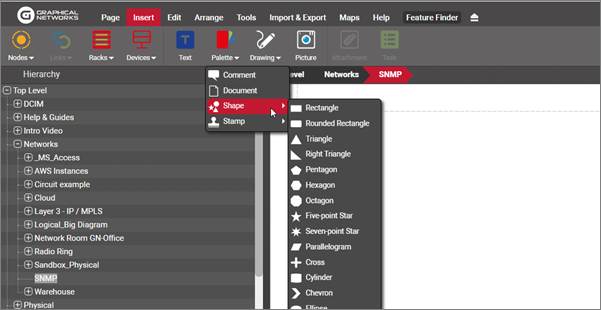
3.4.2.2.2 Inserting text, palette objects and pictures
Users with annotation rights (or better) can insert a series of elements that although are not part of what you would consider the project inventory (nodes, links, devices, etc.) can come in handy to decorate a diagram or provide information related to the project. These elements include free text, palette objects and pictures. We will review these in more detail later throughout the guide.
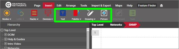
Inserting free text, palette objects and pictures
3.4.2.2.3 Attachments
In the chapter about change management we will analyze in more detail how netTerrain allows you to upload and manage documents as part of your change management process. The attachments button (only enabled when clicking on a node) is used for that purpose.
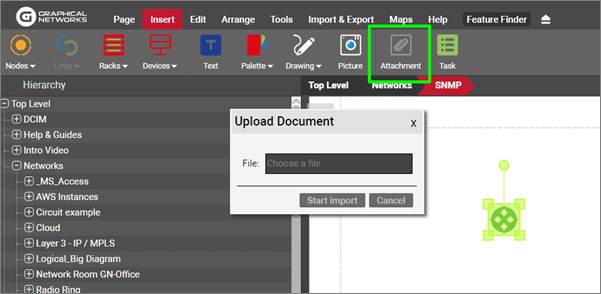
Attachments
3.4.2.2.4 Tasks
Users with sufficient permissions can create and manage tasks associated with nodes to better control the inventory process. The task button (only enabled when clicking on a node) is used for that purpose. To learn more about this change management feature, check out the chapter about change management that goes over more details of the work order and task management process.
3.4.2.3 Edit menu
The edit ribbon contains several functions that help you manage the contents of your diagrams efficiently, including the following features:
- Delete: ability to remove objects from the diagram
- Hide: ability to hide objects on a diagram
- Cut: button to cut an object so that it can be pasted on a different diagram
- Copy
- Copy+: button to copy a node including all its children underneath
- Paste
- Alias: ability to create an alias (mirror image) of a node
- Duplicate: ability to duplicate a link with the same endpoints
- Select All
- Select Type: ability to select all objects of the same catalog type
- Type Table+: ability to open a table view of all the objects of the selected type
- Type Table: ability to open a table view of all the objects of the selected type on that diagram
- D-click rule: ability to edit the double click rule associated with a node
- Attachments: button to edit the attachments associated with a node
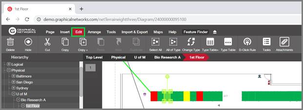
Edit menu
Each of these buttons and features is reviewed in more detail later throughout this guide.
3.4.2.4 Arrange menu
The arrange ribbon contains several functions that help you quickly lay out objects on your diagrams in a myriad of configurations. These functions include the following features:
- Reorder: change the z-order of an object with respect to other overlapping objects
- Center: ability to center objects horizontally, vertically or both
- Resize: bulk resizing operations
- Set Default
- Reset Size
- Arrange: bulk row, column, tile and ellipse arranging features
- Align: left, top, right and bottom alignments for bulk operations
- Layout: Force-directed layout function
- Curve Line
- Straighten Line
- Bend Point: add bend point to a line
- Separate: separate multiple lines sharing the same endpoints
- Undo
- Redo
Most of these buttons and features are reviewed in more detail later throughout this guide.
Attention!
Note that data entry operations are not subject to undo or redo. In other words, the undo and redo only apply to operations of aesthetical nature, such as moving and resizing nodes or adding bend points. Also, the undo and redo work within a given user and session. If you refresh a page you are also refreshing your browsing session and any previous steps are flushed in the undo / redo cache.
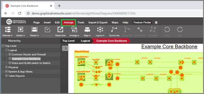
Arrange menu
3.4.2.5 Tools
The tools ribbon contains several miscellaneous functions including:
- Connected: show all objects directly connected to the selected object
- Main Path: show main shortest path between two selected nodes
- Multi-Paths: show main and backup path between two selected nodes
- CLR: Circuit Layout Record diagram
- Bundle: function to associate links with other links
- Query
- Search
- Utilities
Each of these buttons and features is reviewed in more detail later throughout this guide.
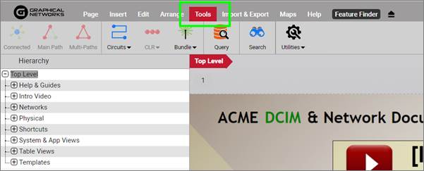
Tools menu
3.4.2.6 Import and export
netTerrain includes several options to import and export data. For imports netTerrain supports:
-
netViz projects
-
Microsoft Visio
-
Excel bulk imports
-
KML / KMZ
For exports it supports the following formats:
- Visio
- PowerPoint
- Static HTML
- PNG
- KML / KMZ
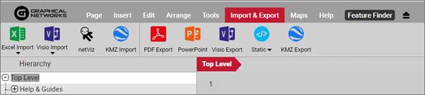
Import & export menu
These features are reviewed in more detail later.
Attention!
netTerrain supports many other import and export functions besides these. These buttons only deal with imports and exports within a given diagram or project. Search results, table views and dashboards support other export formats and netTerrain can also import from databases, discovery processes and much more.
3.4.2.7 Maps
netTerrain includes several features used for outside plant purposes. Some of these functions are accessed from the Maps menu shown below:
-
Map: upload and modify the diagram map
-
Layers: change the map layer
-
Place: place a node on the map
-
Locate: locate a place on a map
-
Measure: measure distances and lengths
-
KMZ Import
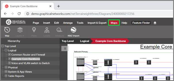
Map menu
The outside plant features are reviewed in more detail later throughout the guide.
3.4.2.8 Help
The help menu includes several buttons to provide support in a variety of areas:
- Videos to help you get started
- Sample projects online
- The “dragonfly” tutorial that can be relaunched
- Animated gifs on how to get started
- PDF guides
- The shortcut (hotkey) list in PDF format
- Utilities (downloads)
- The REST API guide
- Customer portal support link
Help menu in netTerrain
The help menu can also be accessed from the traditional top right corner.
But wait, there’s more: you can access the help menu from the top right corner...
3.4.3 Feature Finder
The feature finder helps novice users find features quickly. The way this works is simple: click on the feature finder button and start typing!
As you start typing in the feature finder dialog, netTerrain displays several options related to the search key. When you hover the mouse over any of the options, the corresponding button that handles that specific option is highlighted.
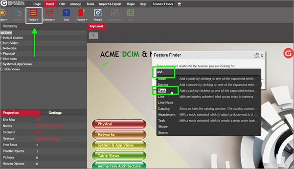
Feature finder
Currently the feature finder only provides help with functionality associated with a button. For help with functions outside the realm of buttons in the ribbon you may have to rely on this beautiful guide.
3.4.4 Quick access bar
The quick access bar provides users with a quick way to access different work areas in netTerrain. Currently netTerrain has the following work areas:
- Project: the main inventory view with its collection of diagrams and tables. All users have access to this area
- Reports: repository of graphical dashboards and reports. All users have access to this area.
- Work Orders: area to manage work orders and tasks. Editors (or better) can access this area
- Catalog: the library of devices, node and link types and other categories of objects. Only power users and administrators can access this area.
- Admin Console: the place to manage users, groups, settings and other admin tasks. Only administrators can access the admin console.
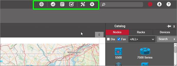
The quick access bar near the upper right corner (in green)
The quick access bar is always present in every netTerrain area. Users can quickly jump from one area to another, if they have the permission level to do so.
3.4.4.1 Project link
The project button shown below takes users back to the Top Level in the project. This button is the equivalent of pressing the top-Level link on the breadcrumbs.

Top level link
3.4.4.2 netTerrain Reports and Dashboards
The reports link takes you to another area in netTerrain displaying several dashboards and reports.

Reports link
Each dashboard presents information graphically using so-called gadgets, which are dashboard items that organize data using visual arrangements, such as:
- Charts
- Pies
- Gauges
- Cards
- Other (maps, pivots, grids, etc.)
netTerrain ships with a series of default dashboards, which can be customized. Users can also create new ones using the netTerrain dashboard editor (see netTerrain Dashboard Designer Guide).
Attention!
Some of the default dashboards provided with netTerrain are geared towards DCIM-type data. If you are a user of netTerrain Logical, those dashboards are not available.
We will review reports and dashboards in more detail towards the end of this guide.
3.4.4.3 Event console
The event console shows several types of events such as alarms, overrides and incoming traps from your network.

Event console link
By clicking on the event console link you access a list of events sorted by timestamp (newest first), including the event type, severity, time received, object affected, description, acknowledged status cleared/resolved status and notes.
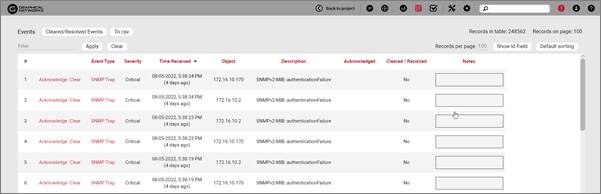
Event console
3.4.4.4 Work order management
The work order management area is only accessible by administrators, since it displays the work orders and tasks created or managed by any user.

Work order link
By clicking on this link administrators access a list of all the work orders that exist in netTerrain.
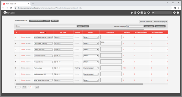
Work order list
From this list, the administrator can drill down into tasks, check overdue tasks, reassign tasks and work orders, manage dude dates and much more. We will view the work orders in more detail later in this guide.
3.4.4.5 Catalog link
Next to the work orders link we have the catalog link, accessible for power users and administrators. As explained above, the catalog is the place where power users can manage the library. For more information about the catalog please check the power user guide.

Catalog link
3.4.4.6 Admin console
As the name suggests, the admin console gives administrators access to a console to manage users, groups, settings and other administrative tasks. This link is not visible to any users other than administrators. For more information about the admin console please check the administrator guide.

Admin console link
3.4.4.7 Last diagram link
When you find yourself in an area other than the main project you can always return back to the project by pressing the go back button on the browser (remember, netTerrain is a browser-based app). However, it may take several clicks until you get to the last diagram you were in before leaving the project side. To the left of the top-Level link, you can find the ‘Back to project’ link which serves as a convenient shortcut that takes you back to the last diagram you visited before you decided to venture outside the netTerrain project area.

Last diagram link
3.4.5 Zooming and panning
netTerrain diagrams can be quite large arrangements of nodes and links, so zooming and panning are common operations. Zooming and panning are operations that only apply to the project area. All the zooming and panning functions are grouped together in a compact toolset that you can find on the lower right corner of a diagram.
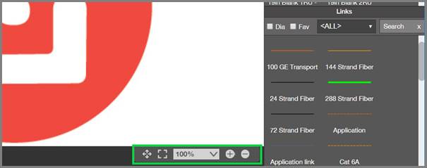
Zooming and panning toolset
3.4.5.1 Zoom options
To zoom, you can use the ‘+’ and ‘-‘ buttons, as well as the keyboard or the mouse-wheel. You can zoom into a specific percentage level by choosing one of the fixed options on the zoom drop-down box. You can also fine-tune your zoom level by typing any value. We’ll review each option below.
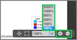
Zoom options
Tip:
A quick way to zoom into any desired area is to ‘paint’ a zoom rectangle by holding the right mouse button and creating a selection area with your mouse (see below).
3.4.5.2 Zoom in
This button lets the user gradually zoom into the diagram by repeated clicking. The hotkey for this operation is the key that contains the ‘+’ sign.

Zoom in button
Besides zooming in using the button, users can also zoom in using the mouse wheel and the right mouse button. With the mouse wheel a user can move the pointer to the part of the diagram that should be centered during the zoom process and then move the mouse wheel to zoom in or out.
To zoom in with the right mouse button, simply press and hold it and the move the mouse to create a zoom in rectangle area. Once the button is released, the diagram is zoomed in.
A zoom in rectangle generated with the right mouse button
The same zoom in function as the button, is also available from a submenu when right-clicking on the diagram.
3.4.5.3 Zoom out
This button lets the user gradually zoom out by repeated clicking. The hotkey for this operation is the key that contains the ‘-’ sign.
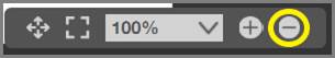
Zoom out button
Users can also zoom out by using the mouse wheel or selecting the zoom out option from the diagram right-click -> zoom menu.
3.4.5.4 Pan
Panning is quite easy using the zoom and pan toolset. Simply press the pan button, which is the left-most button with the four arrows. Once pressed, the cursor changes into pan mode. As soon as you release the mouse button, the pan is again disabled. If you want to pan multiple times in succession you must click on the pan button each time. Instead, keep it simple: use one of the pan shortcuts (see tip).
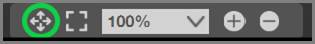
Pan button
Tip:
For continuous panning we highly recommend using one of the shortcuts or hotkeys:
1) Press the shift key while you hold the left mouse button and then move the mouse
2) Press and hold the mouse wheel!
3.4.5.5 Fit to window
This button is used to restore the diagram to a size that fits the entire screen. Typically, this operation is performed after a zoom-in operation.
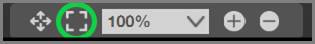
Fit to window button
When you fit the diagram to the window size you may notice that the zoom level indicator (bottom right corner) is at 100%.
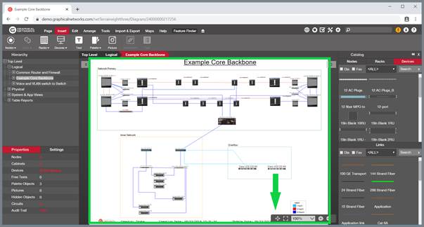
Diagram that was fit to window, with a 100% zoom level
Tip:
Use the ‘w’ hotkey for this button or double-click on the mouse wheel. You will get very used to these convenient shortcuts and save a lot of time on unnecessary mouse trips.
Attention!
If the ‘w’ hotkey seems not to react you may not have the focus on the diagram. Click anywhere on the diagram and try again.
3.4.5.6 Hiding the zoom toolset from the diagram
As you zoom in and out and perform pan operations, the zoom bar can sometimes be a bit intrusive as it is sitting on top of the diagram and cannot be moved. Since all basic zoom operations can be achieved via shortcuts or other menus, some users prefer to hide the zoom bar.
To hide the zoom bar simply right click anywhere on the diagram (or go to the zoom menu) and then click on ‘Hide Zoom Toolset’.
3.4.6 Hierarchy browser
The hierarchy browser in netTerrain provides a quick way to access any sub diagram in the netTerrain project. Items in the browser can be clicked or expanded. When clicking on an item, netTerrain takes the user directly to the diagram corresponding to that item.
The objects that appear in the hierarchy browser include:
1) Nodes that contain other nodes (the definition of a diagram)
2) The current diagram (regardless of whether it contains nodes or not)
3) Devices, assuming the option ‘Display devices in hierarchy browser’ is enabled in the admin console (see Admin Guide)
3.4.6.1 Expanding a hierarchy browser subtree
In some cases, it can be useful to expand all diagrams of a subtree in the hierarchy browser (or maybe the entire hierarchy browser). To do that, hold the control key and click on the parent leaf that you want to expand in its entirety.
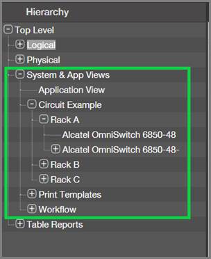
Fully expanded subtree
You can expand different parts of the hierarchy tree independently, so that you can visually the corresponding subtrees simultanously. The subtrees remain expanded even if you click on a particular subtree leaf.
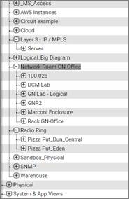
Multiple expanded subtrees even when a leaf is selected
3.4.7 Searching
The netTerrain search engine is fast and simple to use and is based on direct pattern matching.
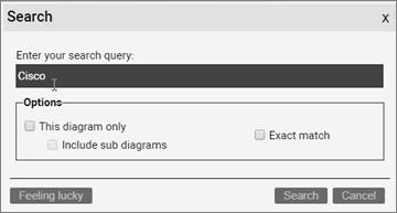
To start a search, locate the search box and enter the text you want to use for searching.
This could be a partial string representing the target object or a full string. Then press enter.

Searching for a string in netTerrain
The search engine will find any records that have a total or partial match with the supplied string (the string is highlighted in yellow within the result set). It then retrieves a list of instances that match the search criteria, with the ability to click on a link to take the user directly to the diagram containing that instance.
The search can also be rerun with a different search pattern straight from the previous search result list. A convenient filter text box lets users filter the search results using any other additional string.
Other features of the search results table include the ability to show or hide the id field, sort by any column, reset to default sorting, refresh the page and jump to other pages in case of pagination.
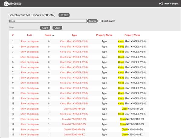
Search result table view example
The user can also click on any link (Show on diagram) and it will retrieve the diagram where the object is contained, along with a blinking rectangle that highlights that object.
In addition to the quick search described above, the tools menu includes a button to open a more powerful search functionality (you can also press “s” on your keyboard) which brings up the search dialog.
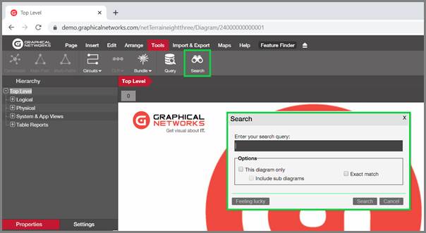
A more advanced search
The dialog lets you search within the current diagram only or the current diagram and below. It also lets you force an exact match on your search, use parameters and utilize the feeling lucky function (more on that later).
Full floating search dialog with suggestions
Attention!
If the ‘s’ hotkey seems not to react you may not have the focus on the diagram. Click anywhere on the diagram and retry.
3.4.7.1 Using search parameters
In addition to partial string matches, netTerrain also allows searches using parameters to limit the results based on different criteria. The character used as an indicator for the parameter is the backslash ‘\’. If any of the supplied parameters (such as a type or property name) contains a space, enclose that parameter in double quotes (including the backslash).
Here is an example of a search using parameters:
This search would retrieve all objects in netTerrain of a type that contains the string ‘site’, that have a property called ‘latitude’ where the value contains the character ‘4’.
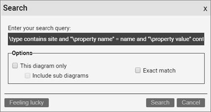
Advanced search using parameters
3.4.7.1.1 Search operators
The following are valid logical operators when running advanced searches in netTerrain:
-
AND
-
OR
-
NOT
-
CONTAINS
-
“(“ and “)”
-
“<“ and “>”
3.4.7.1.2 Finding objects of a specific type
To find all instances of a specific type, the following syntax is valid:
-
\type =
-
\type contains
-
\type not
The following search will retrieve all instances of types for which the type name contains the string ‘500’.
3.4.7.1.3 Finding objects by property name
If you need to find objects of any type, but only those instances for which there is a specific property, the following syntax (and combinations) is possible.
-
“\property name” =
-
“\property name” contains
-
“\property name” not
3.4.7.1.4 Finding objects by property value
If you need to find objects of any type, but only those instances for which there is a specific property, the following syntax (and combinations) is possible.
-
“\property value” =
-
“\property value” contains
-
“\property name” not
3.4.7.2 Feeling lucky searches
Are you feeling lucky today? You can save yourself a couple of clicks if you think your search criteria will retrieve the desired result at the top of the result list. If you think your search criteria will retrieve just one match, then by definition that would also be the first result!
Typically, you then want to navigate to the diagram containing that record, which requires you to get to the search result list and then clicking on the ‘Show on diagram’ link. The “feeling lucky” search saves you that extra step. Simply bring up the floating box, type the search string and then press the feeling lucky button.
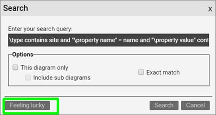
Feeling lucky button
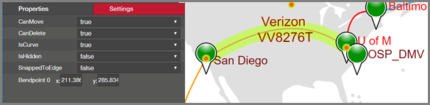
3.4.8 Properties and settings
Every netTerrain diagram includes a properties and a settings dialog underneath the hierarchy browser on the bottom left. The properties tab works in two modes:
1) Diagram mode
2) Object mode
The settings tab lets you adjust some of the object and diagram metadata, including size, position and more.
We will review these tabs in more detail throughout the next chapter.
Properties and settings
3.4.9 Catalog
From the catalog window users can pick objects of different types and drag and drop them into the project. netTerrain has two separate dialogs for the nodes (including devices and racks) and links catalog, as shown in the screenshot below. Users can undock, close, hide or show the catalog window, which will be explained in more detail throughout the guide.
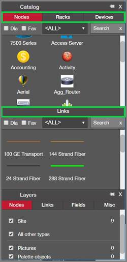
Nodes and links catalog
3.4.9.1 Accessing the catalog for a node type
netTerrain has a nice shortcut to access a node type in the catalog directly from this pane. Simply double click on the node in the catalog pane (here on the project), and netTerrain takes you straight to the catalog, displaying the type in the node type list view.
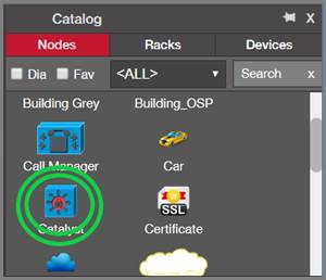
Double-clicking on node item in catalog pane
This shortcut comes in handy to get directly to a catalog definition of a node without having to click through several pages. Notice that you still must be a power user or administrator to take advantage of this feature.
3.4.10 Layers
From the catalog layers users can hide or show objects on a given diagram based on their type. Users can undock, close, hide or show the layers window, which will be explained in more detail throughout the guide.

Layers
3.4.11 Breadcrumbs
As the name suggests, breadcrumbs denote the path the user took to reach the current diagram. Or put another way, the node names that form the breadcrumb correspond to each leaf in the hierarchy the user had to access to reach that diagram.
Breadcrumbs are displayed on top of the diagram itself, as shown in the image below:
Breadcrumbs, yummy...
3.4.12 Work order notifications, user and help menus
On the top right corner of the page, you can find the user and help menus, and if any work order notifications exist for the current user, these are shown to the left of the user menu, as pictured below:

Notifications, user and help menu
The help menu is essentially the same set of help options that you find in the help ribbon. For the user menu, the following sub menus are available:
- My work order tasks: opens the list of work orders for the current user, as explained later in the guide
- User settings
- Log off link
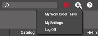
User menu options
3.4.12.1 User settings menu
The user settings menu is your own space that lets you personalize netTerrain. You can access this menu by clicking on the user icon and then selecting the ‘My Settings’ sub menu.
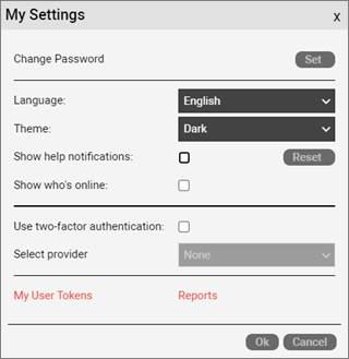
User settings dialog
3.4.12.1.1 Changing your password
To change your password, simply click on the ‘Change Password’ menu and fill out the form accordingly. You must provide your current password to change it to a new password successfully. When all else fails, you can always request a password change from the sys admin.
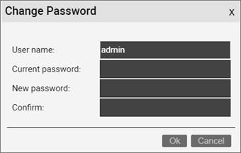
Changing your password
3.4.12.1.2 Language settings
Users can change their own language settings. For example, if you live in sunny Mexico, Spanish is one of the four languages we currently support. The languages that are currently supported include:
-
English
-
Spanish
-
French (Canadian French)
-
Simplified Chinese
3.4.12.1.3 Themes
The next setting is a fun one: you can switch the theme or skin to match the colors of your favorite sports team.
The ‘Show help notifications’ option lets you turn these notifications on or off. And if you’d like to get help notifications as if you just started using netTerrain, simply click on the reset button.
When the ‘Show who’s online’ checkbox is checked, you will see the users that are currently on netTerrain or the same diagram you are navigating.
3.4.12.1.4 Using two-factor authentication (2FA)
If you would like to harden the security settings for accessing netTerrain, you can implement a two-factor authentication (2FA or MFA) mechanism for your netTerrain login. To do this follow these steps:
- Open your user settings dialog
- Check the “Use two-factor authentication” box
- Press “Set”
- Install the “Google Authenticator” app on your mobile device. It can be downloaded from the Google Play or Apple store.
- Then add a new application (press the + icon) to the Authenticator App and scan the generated QR code. See the screen shots below.
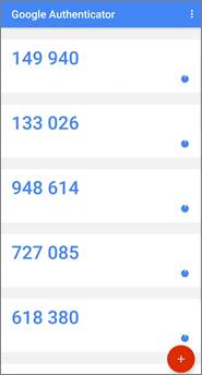
Google Authenticator App
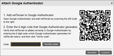
QR Code to scan using App
Once this is completed you can log out of netTerrain and back in. After each login you will be prompted for the google authenticator code.
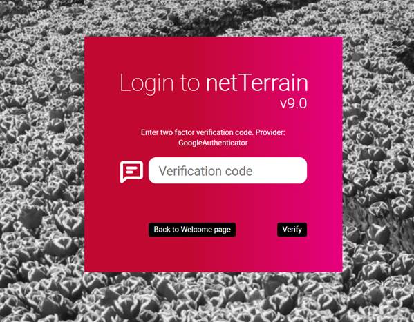
Google verification code dialog
3.4.13 Context menus
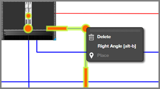
Context menus are essentially menus that pop up when a user right clicks on a diagram or an object. They are a convenient way to find out what can be done in a certain context, so, as we like to say, when in doubt, right-click!
For better usability and easier handling of objects, netTerrain has five categories of context menus, which are triggered by a mouse right-click:
- Diagram context menu
- Node/object context menu
- Link context menu
- Displayed Field context menu
- Free text context menu
- Bend point context menu
If a user wants to open the diagram context menu, for example, a simple mouse right-click on any part of the diagram that is empty will do. The context menu that pops up will then provide a series of sub menu options to perform certain actions specific for a diagram. Note that in many cases certain sub menus are grayed out.
Tip:
Use the shortcuts! You can open any context menu by pressing [alt-c]. For instance, if you select a link and press [alt-c], the link context menu pops up.
This is a very useful shortcut when richt-clicking on an object is tricky (such as a very thin link).
3.4.13.1 Diagram context menu
The diagram context menu includes most of the functions related to the diagram itself. So for example if you want to upload a background, select all objects or insert an object, simply right-click on the diagram and click on the desired sub menu.
Make sure that when you right-click, it is on the diagram itself and not some other object, because this would bring up a different context menu. Also remember to use the [alt-c] shortcut!
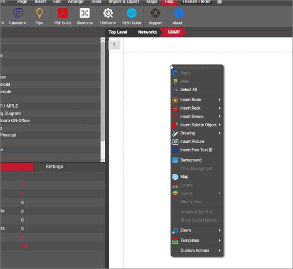
Diagram context menu
We will review the details of each operation throughout the rest of the guide.
3.4.13.2 Node Context menu
The node context menu shows several node related operations such as deleting, connecting, cutting, copying and more.
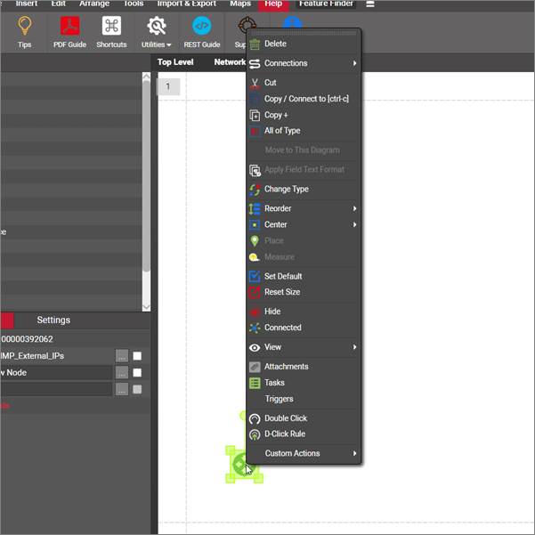
Node context menu
We will review the details of each operation for nodes throughout the rest of the guide.
Attention!
Be careful when selecting objects: the menus that are enabled differ when you have multiple objects selected as opposed to just one.
3.4.13.3 Link context menu
The link context menu shows several link related operations such as deleting, copying, reordering and much more.
An easy way to bring the link context menu is to simply “touch” a link with a selection rectangle by holding down the left mouse button and dragging the mouse towards the link (no need to carefully right-click on it, as that may require good pulse if the link is too thin) and then pressing [alt-c], which, as you now know, is the shortcut for the context menu.
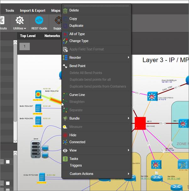
Link context menu
We will review the details of each operation for links throughout the rest of the guide.
Attention!
When you want to bring in the link context menu make sure you are not just clicking on one of the bend points. Bend points have their own special context menu.
3.4.13.4 Displayed field and text context menu
They may look similar but displayed fields and texts are not quite the same category of entity: displayed fields are associated with a node or link whereas text is untied (free floating in a diagram and not associated with any object in particular). As such, their context menus vary quite a bit.
Displayed fields have an array of options around default settings for the type and applying settings across all occurrences of that displayed field in a diagram:
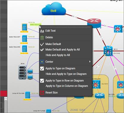
Displayed field context menu
Below we review each sub menu:
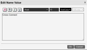
- Edit Text opens the standard text editor for that displayed field. Here, users can edit the displayed field text just like any other free text with plenty of formatting options and the ability to set up expressions (ore on that later).
- Make Default: this option makes the current displayed format the default for that field and type, without affecting existing instances
- Make Default and Apply to all: this option makes the current displayed format the default for that field and type, and applies that format to all occurrences of that field and type currently in the project
- Hide and Apply to all: clicking on this option is the equivalent to deleting the displayed field for every occurrence (of that field and type) in the project
- Center: centers the text with respect to the object horizontally, vertically or both
- Apply to Type on Diagram: applies the current format to all objects of the type on the current diagram
- Hide and Apply to Type on Diagram: hides that field for that type for every instance on that diagram only
- Apply to Type in Row on Diagram: applies that displayed field format for that field and type for every occurrence on that same row on that diagram
- Apply to Type in Column on Diagram: applies that displayed field format for that field and type for every occurrence on that same column on that diagram
- Reset Size: quite self-explanatory, this option resets the size of the text to the default in the catalog
Free text has several options related with copying, cutting, reordering and more. As shown in the image below.
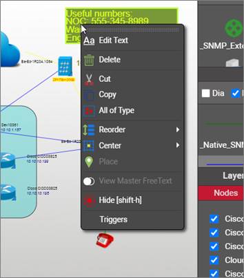
Free text context menu
We will review the details of each operation for displayed fields and text throughout the rest of the guide.
3.4.13.5 Bend point context menu
To activate the bend point context menu, just right-click on a bend point:
Bend point context menu
We will review the details of each operation for bend points throughout the rest of the guide.
4 Working with diagrams and objects
This chapter will show you how to work with diagrams and objects and performing data entry operations on nodes and links. If you have a very large list of objects that need to be added (100+), you may want to consider using the Integration Toolkit (ITK) to automate and speed up the data entry process.
Data entry operations in netTerrain include the insertion of new objects, updating existing objects and deleting existing objects from their diagrams.
Attention!
Full data entry functions are only available to users with editor rights, or higher. Users with an ‘updater’ role may only change data for existing objects.
4.1 Basic operations on diagrams and objects
At its core, netTerrain consists of diagrams that contain two types of objects that represent the diversity of systems that can be created in the tool: nodes and links. Like other familiar tools such as Visio, users have an array of features to make objects aesthetically pleasing and accurate. These features can control things such as properties, size, rotation and settings.
4.1.1 Properties and settings
Every netTerrain diagram includes a properties dialog underneath the hierarchy browser on the bottom left. The properties dialog works in two modes:
3) Diagram mode
4) Object mode
When no object is currently selected, the properties window is in diagram mode and shows a context specific set of properties related to the diagram. For example, if a user drills down into a network diagram, the information displayed initially contains aggregated data counts for underlying nodes and links. This information is diagram, not object specific.
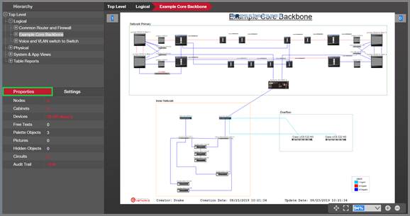
Diagram properties on the top left properties window
A user can click on a specific object (node or link) and view the object specific properties for that object. In this case, the properties window is in object mode and the fields and values displayed will vary based on the type of selected object.
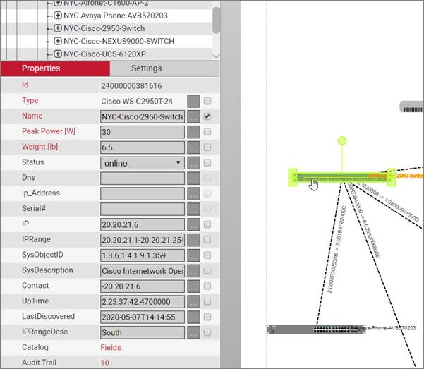
Node properties
Note that the values for a given instance are being retrieved in real-time from the netTerrain database.
Next to the properties tab, netTerrain has a context specific settings tab. Just as with the properties, when no object is clicked, the settings tab shows settings for the current diagram. When a node or link is selected, the settings for that object are displayed.
The diagram settings tab contains a locking option, page size, orientation, margin, template section and a grid settings section. The templates section is discussed later in the guide.
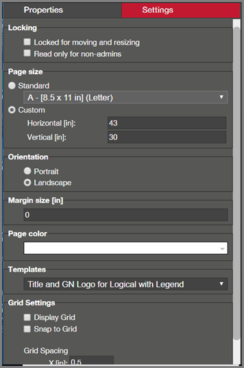
Display section for diagram settings
We will review the diagram display filters in more detail later.
4.1.1.1 Locking objects on a diagram
As an editor, when you zoom in or pan around a project it is easy to accidentally bump an object out of its original position when the diagram has many objects in it. To prevent this from happening, the locking section has an option called ‘Locked for moving and resizing’, which, when checked, disables any moving or resizing for all objects on the diagram.
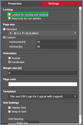
Lock option
Attention!
If some objects are locked within the diagram, as opposed to the whole diagram being locked, whenever the lock option for the diagram is enabled and then turned off, all objects in the diagram will be unlocked.
An additional locking option that controls the level of permissions users have on a specific diagram is the “Read-only for non-admins” option.
This option is useful when you want a root diagram to be blocked from editing, even is users of edit permissions on the rest of the project. This is typically used in conjunction with diagram permission exceptions. For example, you may use the top level as the root access for different groups across the organization, who need edit permissions in their specific sub trees, but you want to make sure they cannot add new nodes to the top level. That’s when this feature comes in handy.
4.1.1.2 Page sizes
In many cases a user may want to change the size of the area that is used to render objects on a diagram. For that purpose, netTerrain has a series of page setup features in the settings tab, to control the look and feel of the page for that diagram. When a diagram is resized, objects on a diagram are also resized to adjust to the new diagram scale.
To change the page setup for a diagram, go to the settings tab and choose from the following options to control the page setup:
- Standard page size
- Custom page size
- Orientation
- Margin size (margins can also be filtered out)
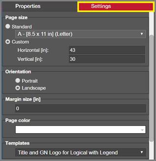
Page setup features
Any changes to the page setup affect all users of the system and can only be set by users with edit rights or better.
Standard page sizes in netTerrain include most North American and European page sizes, such as European A0 to A10, Arch A to Arch E3, and A to E sizes.
When resizing a page, netTerrain will keep the absolute size of the objects. This means that when changing to a larger page size, objects will look smaller on the screen. Conversely, when changing to a smaller page size, objects will look larger on the screen.
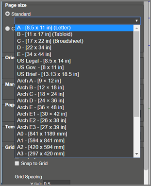
Standard page sizes
Attention!
Be careful when switching to a smaller page size: netTerrain does not allow objects to be out of bounds, in which case nodes and links may end up cobbled together on the bottom right corner. Also, a page resize cannot be undone, so be careful when changing page sizes and make sure the size is really the one you need!
4.1.1.3 Node and link settings tab
When a node is selected, the settings tab exposes certain node (meta) properties related to its appearance and behavior on a diagram. Of interest are the properties that control whether the node can be deleted, moved, resized and so on, as depicted below.
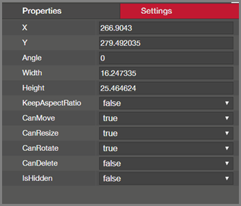
Node settings tab
The settings tab for a selected link has a similar set of properties, which control the appearance and behavior of the link on the diagram, as depicted below.
Object settings for links
4.1.2 Selecting and copying objects
To select an object or set of objects (nodes, links, etc.), users can either click on the object itself or touch it with a selection rectangle. In most cases a simple selection consisting of a click of the left mouse button will do. Note that in the process of selecting an object, the mouse pointer changes from a selection pointer to a hand. This indicates that the object itself is now selectable.
Users may else multi select by holding the ‘ctrl’ key and clicking the left mouse button, but sometimes the user may want to choose multiple objects that are close together or on top of each other, in which case a selection rectangle is the better choice. This can be constructed by holding the left mouse button and dragging the mouse until any part of the object or group of objects is “touched”, as displayed below.
Selecting multiple objects
Once an object is selected it will display a green selection rectangle, which may include four small selection handles on each corner defined by the enclosing object rectangle, and a rotation handle. If these handles are missing is because the object may have the resizing and/or the rotation properties disabled. These settings are reviewed later in the chapter. Note that when an object is selected, any associated displayed fields will present an orange shadowing. This is for the users convenience to quickly identify which displayed fields are tied to that object. This comes in handy when the displayed field is far from the object or it is not obvious that it is linked to it. This feature is also available for links.
Selected node with highlighted displayed fields and handles
Selected links will display an orange overlayed line on top of the link, including augmented endpoints and corresponding bend points.
Selected links with highlighted endpoints and bend points
4.1.2.1 Select all and select of all type
Besides using the ‘ctrl’ key or a selection box, netTerrain offers other ways to conveniently select multiple objects at once.
Users can select all objects on a diagram by right-clicking on the diagram and selecting all objects (ctrl-a). If all objects of a certain type need to be selected, a user can also right-click on any object of that type and clicking on ‘select all of type’. This will select all instances of that type on that particular diagram.
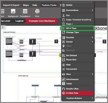
Selecting all of type
4.1.2.2 Copying objects
An easy way to copy objects is to use the standard windows-style clipboard functions and shortcuts. A big advantage of copying objects that not only do you create an instance of the same type, but also the pasted object preserves the property field values of the copied object. To copy an object to the clipboard simply right-click on the object and then click on the ‘copy’ button. An even easier way is to select the object and press the Ctrl-c shortcut.
Once the object has been copied, simply press ctrl-v, to paste the object.
If notifications were turned on by the administrator, once the object or objects you will see a yellow notification indicating the number of objects copied to the clipboard.
If notifications were turned on by the administrator, once the object or objects you will see a yellow notification indicating the number of objects copied to the clipboard.
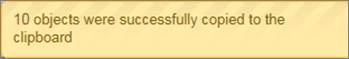
Copy to clipboard notification
A simple way to place a copied object is to use the right-click context menu and paste option. Simply position the mouse cursor where you want the copied object to be placed. Then select the paste option from the right-click menu.
Attention!
Note that reference nodes cannot be copied to the clipboard. netTerrain automatically disables the copy button for any selected objects that cannot be used with the clipboard.
4.1.3 Moving, cutting and rotating objects
Moving objects is a trivial task. Select one (or more of them), hold the left mouse button and then move the mouse to the target area on the diagram. Note that the x and y coordinates of an object can also be controlled from the object settings tab.
For fine tuning, the left, right, up and down arrows can also be used to move objects one pixel at a time.
4.1.3.1 Moving objects between diagrams by cutting
We saw before that you can use the clipboard in netTerrain, just like you do in other software packages. One of the most common clipboard operations in netTerrain is to cut an object. This is commonly used to move that object to another diagram, since you cannot move it to your target diagram by dragging and dropping.
Cut an object to the clipboard, by using the ‘cut’ button (Ctrl-x). Once it’s in the clipboard, simply navigate to the target diagram, then right click and paste (or simply press <ctrl-v>).
Attention!
When moving objects from one diagram to another, netTerrain automatically rearranges any connections and reference nodes to reflect the hierarchy changes correctly.
4.1.3.2 Rotating
To rotate an object, select it first and then hover the mouse over the rotation handle. Notice how the mouse cursor changes to a rotation cursor. Proceed to click on the handle and hold the left mouse button as you move the mouse. Note that for better control it is ok to move the mouse ‘away’ from the handle.
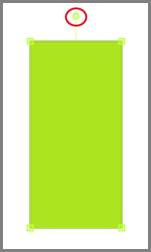
Rotation handle
Also, the object angle can be controlled from its settings tab:
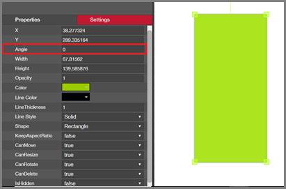
Angle setting for rotation fine tuning
Attention!
If the move or rotation object handle is missing, it means that the object is locked for that operation. If you need to move or rotate an object, click on the object and then from the settings tab, make sure the ‘CanMove’ and/or ‘CanRotate’ options are set to true.
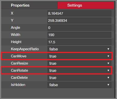
CanMove and CanRotate options
4.1.3.3 Rotating nodes with fixed 30 degree increments
In many instances you want a node to be rotated by a nice multiple or round number. A nice trick in netTerrain is to rotate a node by holding the <ctrl> key, which rotates the node in fixed increments of 30 degrees.
This comes especially handy when you want the object to be horizontal, rotated by 90 degrees or by 180 degrees. Without this trick it could take a few steps of trial and error to get the object to be perfectly level, whereas with the <ctrl> key pressed, it is much easier to obtain a perfect result!
4.1.3.4 Moving objects to front and back
In many cases when objects overlap, users want to control the so called z-order of some of these objects. Objects can be sent to the back of the z-order or brought to the front, with respect to other objects on the diagram.
To do this, simply right-click on the object and select one of the ‘reorder’ options, as shown below.

Changing the z-order of a node
Reordering in the z coordinate is also available for link. For example a link may be shown in front of its connected node or behind it.
You can also change the z-order of objects using the reorder button that you can find in the Arrange ribbon.
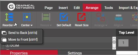
Reorder button in the arrange ribbon
Tip:
Use the shortcuts! For the ‘Move to front’ and ‘Send to back’ options you can use [ctrl-b] and [ctrl-f].
4.1.4 Resizing objects
Resizing an object in netTerrain is a very simple task. Simply select the object and then drag one of the resize handles to change the size.
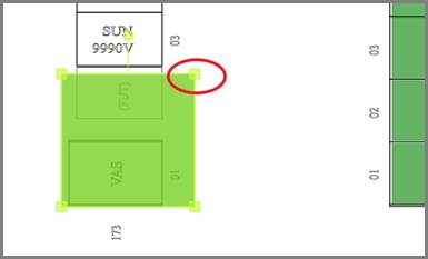
Resizing handle
Attention!
If an object retains its aspect ratio, this is because the KeepAspectRatio option in the object settings tab is set to true. Also, if the resize object handle is missing, it means that the object is locked for that operation. Change the CanResize option as needed.
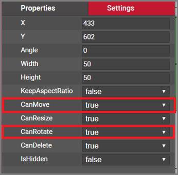
CanMove and CanRotate options
4.1.4.1 Resizing objects in bulk
The resize options work on any type of object in netTerrain, including nodes, palette objects, images and free text. netTerrain provides a menu for the main bulk resizing operations, which include:
- resizing to shortest
- resizing to widest
- resizing to narrowest
- resizing to tallest
Any of these operations work over the current set of objects selected by the user. Note that if the diagram forces objects to keep the aspect ratio, then the smallest dimension will be utilized as a reference for resizing.
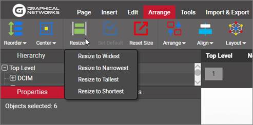
Resizing a set of objects
4.1.5 Aligning and arranging objects in bulk
In many cases users need to align, arrange or center multiple objects on a diagram, in which case it is convenient to use bulk operations, instead of working with single objects at a time.
As a faster alternative to individual arranging and resizing, netTerrain offers two convenient menu options.
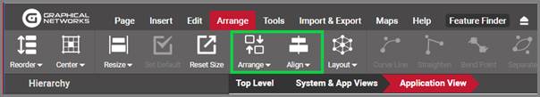
Arrange and resize button
The arrange button lets users arrange a set of objects in a row, column, tile or ellipse as well as left, right, top and bottom alignment. An additional graph layout algorithm called ‘Force directed layout’ helps a user spread out connected nodes to minimize crossings. Users select the objects that need to be arranged using the selection button and then proceed to select the best suitable arrange option.
4.1.5.1 Row and column arranging
Options for row and column arranging include the ability to sort objects in ascending or descending order. First select a set of objects and click on the ‘arrange’ button and select the arrangement type (for example row). The following options are available:
-
Ordering:
-
None: keeps the current relative position of objects (by x coordinate for row arrangement and y coordinate for column arrangement)
- Ascending: orders objects in ascending order by name
- Descending: orders objects in descending order by name
-
Odd and Even: sorts the objects into odd and even groups
-
Spacing method:
-
Edge to Edge: the spacing is determined by the distance between object edges
- Fixed interval: the spacing is determined by the distance between the object centers
-
Fixed spacing: when checked, provides the spacing distance, when unchecked the row boundary is determined by the x coordinates of the left and right most-objects before the arrangement took place
-
Centering:
-
Vertical: the ensuing ordered row will be vertically centered with respect to the page
- Horizontal: the ensuing ordered row will be horizontally centered with respect to the page
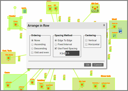
Arranging a set of objects in a row
4.1.5.2 Tile arranging
Users can create “object matrixes” with predefined row and column dimensions, using the tile arrange feature. In addition to the options above, tile arrangement also provides the option of selecting the number of rows or columns for the object matrix.
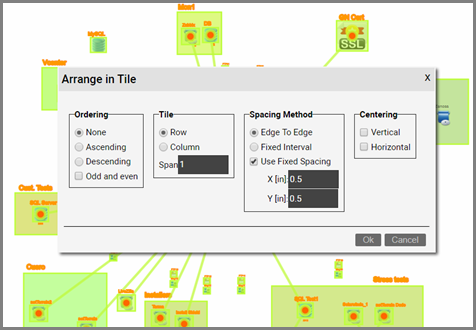
Arranging a set of objects in tile
4.1.5.3 Ellipse arranging
Besides row, column and tile arrangements, netTerrain provides a convenient way to arrange objects in an ellipse, as shown in the diagram below.
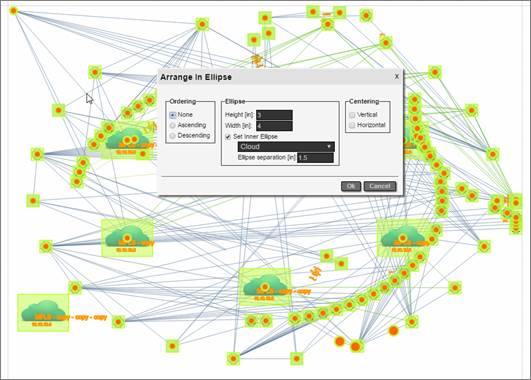
Ellipse layout
The ellipse layout can arrange objects in two ellipse “layers”, where the internal layer is comprised of a set of objects of a certain type and the external ellipse of all the other objects connected to the first layer. Ordering of objects, separation between ellipses and the height and width of the internal ellipse, as well as the centering of the resulting ellipse with respect to the page are the other options for this algorithm.
Note that if the size of the ellipse triggers some objects out of bounds, they are squeezed inside the drawing area determined by the page margins. netTerrain does not like to put objects out of bounds!
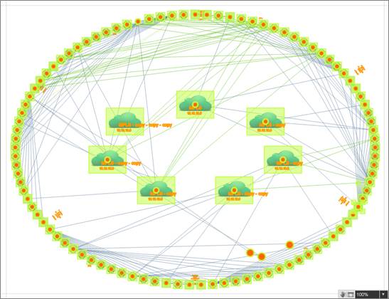
Object distribution after applying ellipse layout
4.1.5.4 Force-directed layout
This feature works in conjunction with connections, so it only applies to nodes.
In some cases, you may want to have a large set of nodes and links automatically dispersed within a diagram. For instance, when you perform a discovery operation and a large set of devices and links are automatically added within a diagram, they are usually cobbled together in a bundle of nodes and links on the top left corner of the diagram. It can be very time consuming to try and place these nodes and links manually. With the ‘Force-directed layout’ algorithm we can spread out nodes and links and minimize link crossings for improved diagram readability.
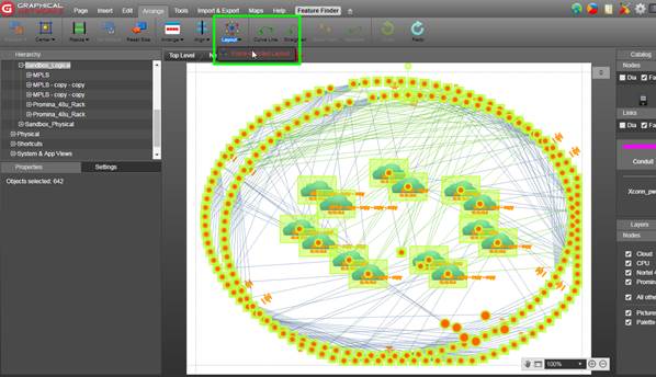
Diagram with nodes and links before applying a force-directed layout algorithm
The algorithm includes a setting referred to as the “energy level”. Low energy level values translate into less link crossings but also higher processing times for running the algorithm. The energy level value can be set between .01 and 1.
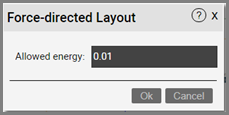
Energy level setting
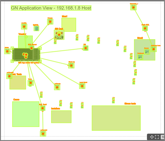
Diagram after the 'Force directed layout' was applied
4.1.5.5 Left, top, right, bottom alignments
In many cases users want objects on a diagram to be aligned in one dimension, while maintaining the same relative position in the other dimension. For that purpose, netTerrain has the option to align objects based on the left-most, right-most, top-most or bottom-most object in the selection.
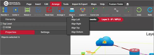
Left, top, right and bottom object alignment options
Below, we show some screenshots after a left and a top alignment operation.
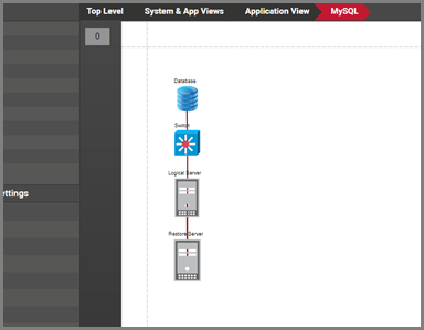
Objects after a left alignment operation
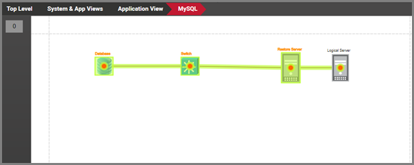
Objects after a top alignment operation
4.1.5.6 Centering objects
Users can automatically center objects horizontally, vertically or both by right-clicking on the object and clicking on one of the three centering options available.
For example, to center a node horizontally, select the node and then click on the ‘center horizontally’ submenu.
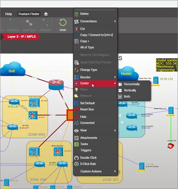
Object centering
You can also change the centering of objects using the Center button that you can find in the Arrange ribbon.
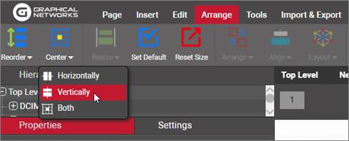
Center button in the arrange ribbon
4.1.6 Diagram backgrounds and grid
Node diagrams can contain background images, which are used to enhance the navigation and look and feel of the project. If you don’t want to upload a background image, yet want to provide a bit of sizzle to your diagram, you can change the background color.
4.1.6.1 Uploading background images
netTerrain supports the following formats for background images:
-
Raster formats:
-
jpg
- png
- gif
-
bmp
-
Vector format:
-
svg
Background images stretch to the whole page size and cannot be selected or resized. To upload a background image simply click on the upload background button found under the Page menu and select an image file from any local or network drive.
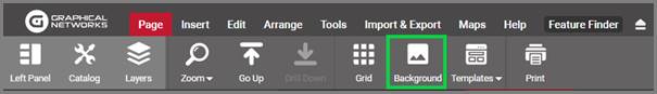
Background upload button
Once selected, the image will be uploaded to the server and rendered on the diagram. You can also use the diagram right-click context menu to accomplish the task.
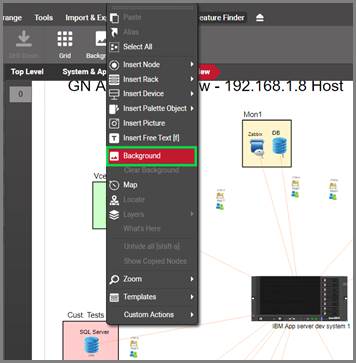
Uploading a background image using the context menu
4.1.6.2 Clearing a background image
A background image can be cleared from the diagram by right-clicking and selecting ‘Clear background’.
Note that the ‘clear background’ option removes the background completely.
4.1.6.3 Hiding a background image
If you just need to hide the background you can simply filter it out by using the background checkbox in the diagram “Layers” Misc settings.
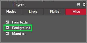
Background filtering
Attention!
If a background does not show up after being uploaded it may be because the Background option in the diagram settings page is unchecked.
4.1.6.4 Changing the diagram background color
An administrator can set up the default background color of a diagram (usually white) but users can override that color on a per diagram basis. To change the background color of a diagram, click on the settings tab (in diagram mode) and select a color from the ‘Page color’ groupbox, as shown below:
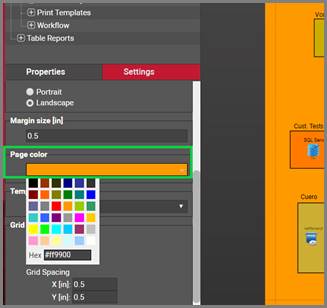
Changing the default page color of a diagram
4.1.6.5 Defining a diagram grid
For any node diagram (that is, a diagram that is not inside a rack, device or card) you can visualize a grid and define the grid spacing.
To enable the grid on a diagram simply click on the grid button on the Page menu:
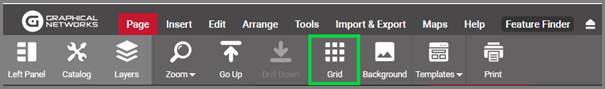
Grid button
Alternatively, you can check the grid checkbox on the diagram settings tab:
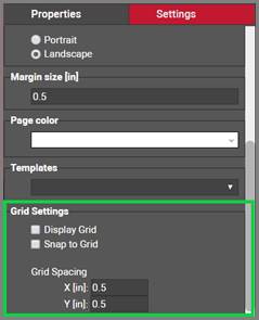
Grid settings
When you enable the grid for a diagram, the default spacing of 0.5 inches is shown, and objects will automatically be snapped to the grid. When enabling the grid through the setting, the snap to grid options is enabled through an additional checkbox, as displayed in the image above. In short, any objects dropped onto the diagram or moved will snap to the grid.
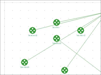
Diagram grid with snapped objects and a 0.5-inch separation
From the diagram settings tab you can change the snap to grid setting, as well as the x and y coordinate grid spacing.
4.2 Working with nodes
netTerrain diagrams are hierarchical in nature; hence you start by adding the highest-level nodes at the top level. For instance, if you want to document your network based on regions, then you would place nodes of type ‘region’ at the top level (perhaps on top of a world map). Because netTerrain lets you model any type of object in the catalog the options are infinite. Customers have also segmented their network views based on department, end-user type, technology or geographical location.
Before we dive into data entry aspects, we will devote a few sections on the drag and drop catalog.
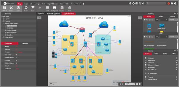
Example of a network view
4.2.1 Understanding the netTerrain catalog
The netTerrain catalog is the repository of all types that exist in netTerrain and it provides an easy way to work with standardized objects. These standardized objects (nodes, links, racks, cards and so on), have a predefined and customizable set of images, properties and behaviors, which makes it easy for an organization to agree on how entities should be represented.
4.2.1.1 Viewing the catalog
By default, the catalog is displayed and docked on the right-hand side of the page:
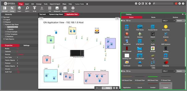
netTerrain node and link catalog
If you can’t see it, just go to the Tools menu and click on catalog. Alternatively, you can click on ‘F3’ (netViz says hi!):
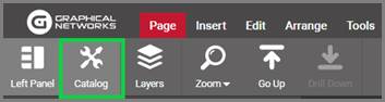
Showing the catalog
Now the catalog should be displayed. You can work with the catalog in docked mode, or you can make it “float” on the diagram and display it anywhere you want. To do that simply click on the “Undock/Dock” handle on the top right corner of catalog, as displayed below:
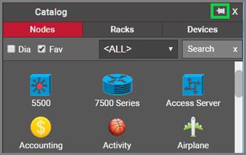
Undocking the catalog
When the catalog is undocked, or floating, you can move it around freely on the diagram by dragging it from the top bar (notice the move mouse cursor). You can also resize it by dragging the bottom corners.
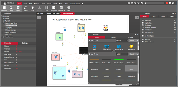
Floating catalog
4.2.1.2 Catalog structure
The catalog is divided into two main categories: nodes and links. The nodes catalog has, in turn, three tabs: one for all the nodes, another one for all the devices and a third one for racks. In total, the catalog has for sections (three for nodes and one for links).
Attention!
Devices and racks are only available for customers that have a valid DCIM license. netTerrain Logical customers will only see the nodes tab.
Each of these sections has four convenient utilities that help you find your objects faster, a ‘Dia’ and a ‘Fav’ checkbox, a ‘categories’ drop down box and a search tool. Whatever settings you pick for these utilities, they are remembered on a per user and per tab basis, even after you finish a session.
4.2.1.3 ‘Dia’ and ‘Fav’ checkboxes: objects on the diagram and favorites
If you hover the mouse over the ‘Dia’ checkbox it reads “Only on the diagram”. As that tooltip suggests, when the ‘Dia’ checkbox is checked, the objects you see in the catalog will only include types that already exist in that diagram.
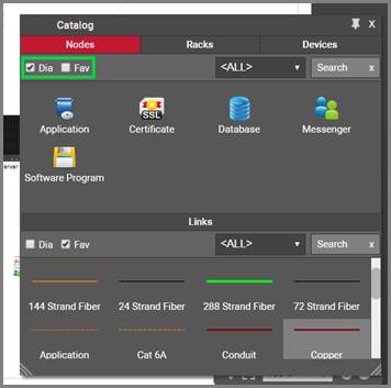
Working with the ‘Dia’ and ‘Fav’ checkboxes
By checking the ‘Fav’ checkbox, the catalog only displays objects that were marked as favorite.
4.2.1.4 Categories drop down box
netTerrain categories are akin to Visio stencils. The default netTerrain installation already includes several categories for nodes as displayed in the screenshot below:
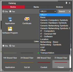
Default node catalog categories
Power users can add more categories, remove existing ones, mark or unmark them as favorites and assign individual objects to those categories. The <ALL> category is always present and, as its label suggests, displays all nodes from all categories (assuming, of course, that the ‘Dia’ and ‘Fav’ options are not checked, and the search string is empty).
We suggest organizing the catalog in a way that is easy to search for different object based on categories and then utilizing the drop-down option to narrow down your searches.
For devices, netTerrain will display the set of vendors that exist in the catalog as the categories for you to filter the devices in the catalog. For instance, if you choose the 3Com category, only 3Com devices will show up, as shown below.
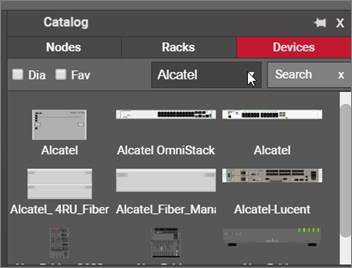
Using the vendor category filters
You can create custom categories for devices, so in case you prefer to use yours, instead of the system-generated vendor categories, contact your netTerrain administrator who can disable them from the admin console (see Admin Guide).
4.2.1.5 Catalog search box
The catalog search box provides the ultimate tool for quickly finding the desired object from the catalog. This is a dynamic, partial string-matching search tool. As you start typing, the set of objects narrows down so that, on average, you probably find your object by just typing 3 or 4 letters.
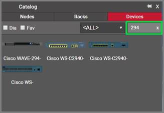
Catalog search
Attention!
We should not confuse this catalog search with the internal catalog search shortcut ‘c’. The former searches for objects in the catalog panes on the project side, the latter searches for types in the internal catalog accessible to power users or admins on the catalog side.
4.2.2 Adding and deleting nodes
Nodes in netTerrain have many behaviors. They can be selected, resized, moved and they can contain an unlimited number of properties. A node is represented by a default image, which can be overridden if any visual overrides are created for that node. Nodes can in turn be the parent diagram of other objects, contained in a sub diagram.
There are several ways of adding a node to your project, including bulk, database, network discovery and API imports. However, in this guide we only review manual data entry techniques. You can review the import/export, ITK and programming guides to explore other methods.
4.2.2.1 Adding nodes by using the node menu
The traditional way of adding a node is from the insert menu. Just click on the left most orange node menu button and several options become available. You can add a generic node, as depicted below, and then change its type to something else, or simply click on one of the categories and find the node type you need.
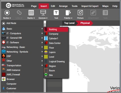
Adding a node using the menu button
The categories and nodes you see here by no means represent the entire catalog. They are just the categories and node types defined as favorites. Categories you see in this menu are user defined and can be modified at will by any power user.
Once you identified the node type you need, you click on it and it will be added to the top left corner of your diagram. This is what we call an instance of a node type, by the way.
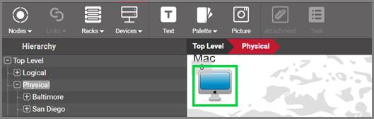
Newly added node instance
Each instance of a node type will reflect the custom properties that were defined in the catalog for that type. In other words, all instances of a certain type share the same specific set of properties.
When you click on that instance, the properties will be displayed on the properties window on your left. Any user with updater permissions or better can modify the values for any of the custom properties.
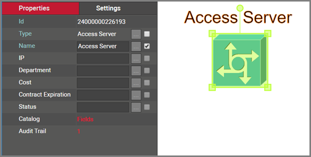
All instances of a certain type share the same properties
As mentioned earlier, if a generic node is added, a user can later change to some other type, by selecting it from the type menu, as shown below.
Attention!
When you change the type of a node, all the properties will change as well. Any data that was filled out for the old node type will be lost, since those properties don’t apply anymore.
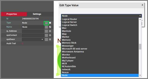
Changing the type for a node
4.2.2.2 Adding nodes by using the right-click diagram context menu
As an alternative method for adding nodes you can do the following:
1) Right-click anywhere on the diagram
2) Click on Insert Node -> desired category or node
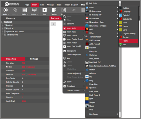
Inserting a node using right-click context menus
The newly inserted node will be placed on the spot where the right-click action occurred.
4.2.2.3 Adding nodes by dragging and dropping from the catalog
The simplest and most powerful method for adding nodes is to just drag and drop them from the catalog pane. To do that, the catalog needs to be displayed. If it is not displayed, just press ‘F3’.
Once the catalog is visible, you can use any of the tools you want to find the desired object:
-
‘Dia’ and ‘Fav’ checkboxes
-
category drop down box
-
catalog search
Once you find your object, just drag and drop it on the diagram. That’s it!
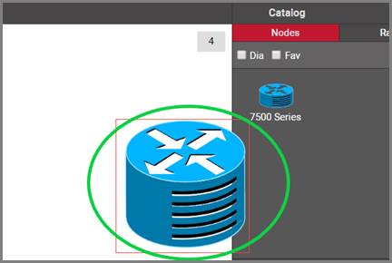
Dragging and dropping a router onto a diagram
4.2.2.4 Adding nodes by dragging and dropping an image from a browser or folder
There is a nice trick to add a node into the project quickly: by dragging and dropping an image from a folder or browser!
The best way to use this trick is to have both the netTerrain browser and the folder or website with the image side-by-side. Then, just drag and drop the desired image to the netTerrain diagram, as shown below:
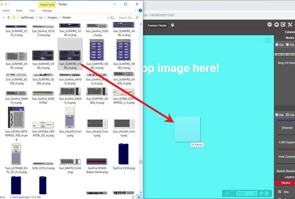
Create a picture by dragging and dropping an image
After you dropped the image on the diagram, netTerrain gives you the option to create it as a floating image (picture), a node type, a device type, or a rack type. Choose the ‘node' option:
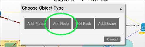
Choosing the 'Node' option to create a new node
This process creates a node type in the catalog using that image. The node type is called something like 'Node #1' and has no custom properties. You can later on (as a power user) edit the node type properties, change the node type name, add new custom fields and overrides and much more. The nice thing about this trick is that it gets you started quickly.
Tip:
You can also perform the same operation by simply copying a picture from your computer with ctrl-c and then pasting it on the netTerrain diagram.
4.2.2.5 Line Nodes
Line nodes constitute a special system defined node type in the catalog that behaves like a node but looks like a link. Line nodes can be connected to other nodes, contain custom properties as well as be pasted as aliases.
There is a system line node in the catalog, but you can also create your own line node types, with custom properties, behaviors and appearances.
Line nodes can be added to a diagram using methods 1 and 2 as explained above. Notice that when you are adding a line node through the context menu (method 2), towards the bottom of the menu you’ll find the line nodes submenu with all the line node types defined in the catalog.
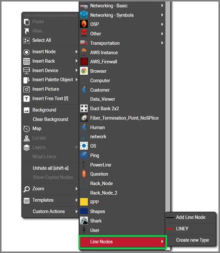
Line nodes
4.2.2.6 Deleting nodes
To delete a node, you can:
- use the delete button in the edit menu
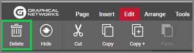
- right-click on the node and click on the ‘delete’ option or
- simply press the ‘del’ key
Note that if objects exist under a node, they will be deleted too, along with any links that either start or end on that node or a child object of that node.
Attention!
If a node has the delete button disabled when selected, it may be because the CanDelete option in the node settings tab is set to false.
Also note that reference nodes cannot be deleted. You need to double-click on one, and go to the diagram that has the original node in order to delete it.
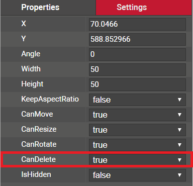
CanDelete option
4.2.2.7 Creating node aliases
A netTerrain project can contain multiple copies of the same node (referred to as an alias). This is useful when a representation of the same object needs to be displayed in different contexts.
The aliasing of a node works in three simple steps:
1) Copy the node (master) that needs to be aliased to the clipboard
2) Go to the diagram that needs to contain the aliased object
3) Click on the ‘Alias’ button in the edit menu or the diagram context menu
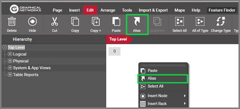
Pasting an object as alias
As a result, an alias of the master will now be placed on the new diagram.
Aliased objects have the following characteristics:
1) The icons for the master and all its aliases are the same.
2) Aliased nodes have a small blue triangle indicator on the bottom right corner.

3) All properties of the master and aliased node are the same and are always in synch (this means that when changing the value of an attribute for an alias, it will change it for every other instance and the master).
4) Deleting any instance (alias or master) will not delete any of the other instances.
The master object on the other hand has a darker alias indicator as shown below.
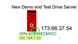
Master node alias indicator
Users can right-click on an alias, and go to the master node, or also right-click on the master node and see a table view of all the aliases associated with that master node, as depicted below.
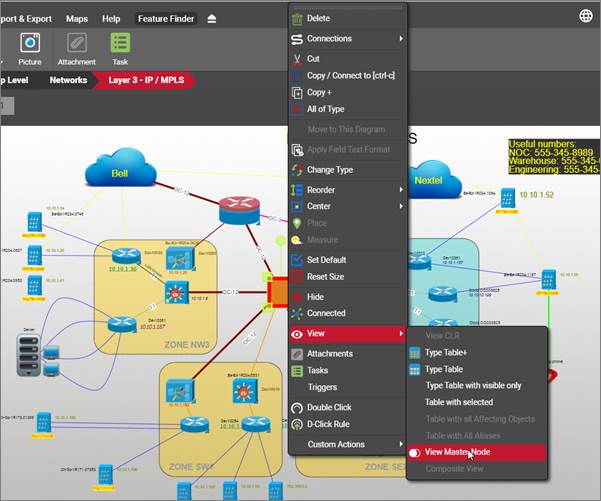
Getting the list of all aliases for a master node
Attention!
Note that whereas aliases can be edited just like any other node in diagram view, they are not editable in table view.
Given an alias, you can also find its corresponding master node by right-clicking on the alias and selecting the ‘View Master Node’ option, as depicted below:
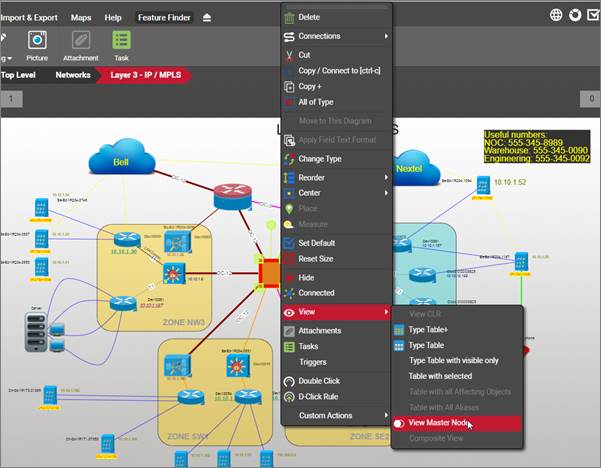
Getting from an alias to its master node
4.2.2.8 Changing the icon for an alias
Aliases share every feature of its master node including properties, property values and icon, since it is a mirror of the master object. An alias doesn’t even have a separate set of property records in the database and it does not increase the license count either.
There is, however, a way for an alias to show a different value of a field than its master, and it’s with the use of an expression. It consists of creating a field that uses an expression to determine its parent node (or node type), and then creating a visual override that changes the icon based on the result. The creation of expressions is outside the scope of this guide (for that, see the Database and Scripting guide) and built-in expressions and visual overrides are reviewed later in this guide and in the power user guide.
4.3 Editing Data
Naturally, as objects are added to the inventory, a user will want to edit node, device and link data. netTerrain provides instance editing capabilities for users with updater (or better) permission levels.
4.3.1 Editing objects
netTerrain is known for its easy and straightforward object property editing. Unlike other tools, where object properties are almost an afterthought, in netTerrain users can edit property values of nodes and links straight from the properties window after a single click.
4.3.1.1 Editing a single object instance by clicking
By simply selecting an object, such as a node or a link, the properties window will display the field values for that object, and make them available for editing.
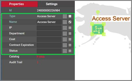
Instance editing
Note that every object has a non-editable Id, which uniquely identifies the record in the database. This Id is internally generated and can come in handy to run searches and easily find unique matches.
4.3.1.2 Combo Box values
Combo boxes (drop-down boxes) allow the selection of values that already exist in a lookup or catalog table in netTerrain. All values for drop down boxes are managed in the catalog.
For faster data entry, users may quickly type the first few letters of the combo box entry when that field is currently selected.
Combo boxes exist for predefined fields (such as type) and can also be created for custom fields (see catalog management).
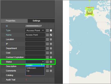
Combo box field
It is important to note that the values in a combo box will only consist of the list values defined in the catalog for that field (and the current value, if it is not in the list).
4.3.1.3 Setting the value to NULL or to a value not in a combo box
It is possible to add values in a combo box field that do not exist in the drop-down list. To do that, simply click on the ellipsis button for the field editor and enter your value there (see ‘Field Editor’ section below). This is also the proper method to set a combo box value back to nothing (NULL).
Attention!
A combo box field may have been restricted in the catalog in such a way that it doesn’t accept manual editing of data.
4.3.1.4 Field editor
In certain cases, a user may prefer to insert long texts by opening the field editor window. This editor can be moved within the main window area and resized. Line breaks can be easily inserted here, by simply pressing the enter key.
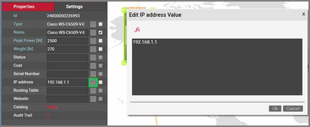
Field editor window
In the field editor you can also add expressions, which are described below.
4.3.1.5 Inserting expressions
Expressions in netTerrain are aggregate SQL functions that exist in the application server. These functions retrieve a scalar value based on the expression query, for example the number of nodes in the project.
netTerrain ships with several predefined functions, and advanced users can also create their own expressions and put them in the SQLexpressions folder on the server (see Database and Scripting guide).
These expressions will then be available to the client and can be displayed on the properties window or on the diagram as a displayed field.
To use an expression, type it on the properties field directly if you know the syntax, or retrieve it from the field editor by clicking on the ‘Exp’ button as shown below.

Adding an expression to a field
The example above shows a node, for which the field ‘AggregateValue’ displays an expression consisting of the total number of nodes in the project. The property field uses the following syntax:
A sample calculated result is shown in the screenshot below.
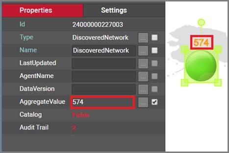
Result of the expression
4.3.2 Displayed fields
Objects shown on the diagram can also include a displayed field for any of the fields associated with that object. The displayed fields will ‘float’ next to the object in any position chosen by the user, and as the object moves, so do the displayed fields.
Each object will have a default set of displayed fields corresponding to its type, but users can override these defaults by selecting the displayed fields on an instance by instance basis, as depicted below
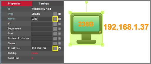
Fields checked as displayed
Tip:
Displayed fields can also be edited directly by double-clicking on them. This is only true if the display field is not directly above the object. If it is above the object double-clicking will drill down into the object. In this case you would need to right-click the text in order to edit the text.
Attention!
For a displayed field checkbox to be enabled, the field cannot have an empty value.
Users can also resize each displayed field, as well as change the font type and color. Displayed fields can be italicized and set as bold, as well as underlined. Each displayed field can be restored to its default setting, or set as a default for that type by simply right-clicking on it and clicking on the corresponding context menu option
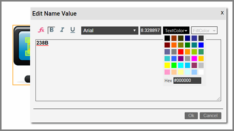
Changing the displayed field appearance
Displayed fields and free text can also be aligned. You can left, center or right align displayed fields or free text, by clicking on it, and selecting the proper justification from the TextAlign feature in the settings tab. You can also choose the justification of top left or center from the settings tab.
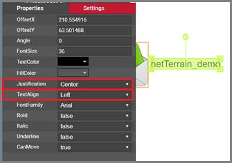
Justification and alignment options for a displayed field
For links, displayed fields can also have a default anchor position. The options are “from node”, “center of link” and “to node”. The “from node” and “to node” position the displayed field near the starting or ending node. The “center of link” will position the displayed field on the center of the link.
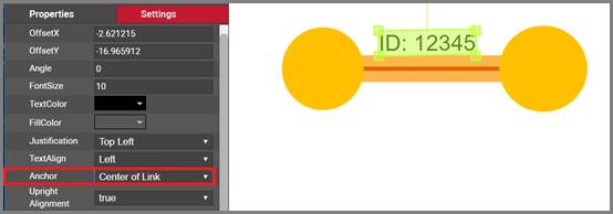
Anchor option for links
4.3.3 Hyperlinks
Any editable field in netTerrain can serve as a hyperlink, which in turn can either open a web page or a document. In that sense, hyperlinks in netTerrain behave as any link in a web browser.
Hyperlinks can be useful for redirecting the user to another web page, for opening a document (the application that reads the document format needs to be installed on the local machine) or even for taking the user to a different diagram within netTerrain (internal link). For internal links, use relative paths that do not include the server name, IP address or application path.
Hyperlinks can be defined for both the field in the editor, as well as the displayed field.
To create a hyperlink simply open the field editor and type in the displayed field between square brackets and the actual URL between round brackets, just as depicted in the image below. If the field is also a displayed field, double-clicking on it will open a new browser tab with the corresponding URL.
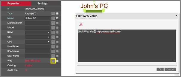
Formatting a field as a URL
Tip:
You can open any hyperlink in a new tab by simply holding the ctrl key while clicking!
Attention!
Note that for the hyperlink to work correctly you need to prefix it with an ‘http://’ or ‘https://’.
4.3.4 Double-click Behaviour
The default behavior for a node double-click action is to drill down into its sub diagram. netTerrain also lets you overwrite this behavior with some other event. To use this feature, follow these steps:
1) Right-click on the object where you want to overwrite the double-click behavior
2) Choose the ‘D-click rule’ option
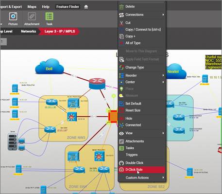
3) Then choose from one of the available options, as shown in the screenshot below:
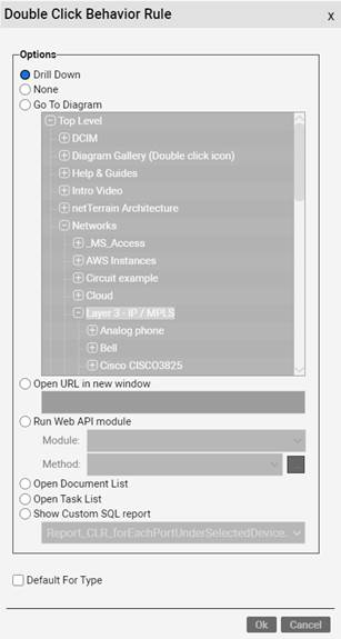
These are all the options to override a double-click behavior:
a. The ‘Drill down’ option is the default behavior. This opens a sub diagram for a node object or a backplane for a device.
b. Selecting “None” will prevent any double-click behavior for the object.
c. The ‘Go To Diagram’ option allows you to re-direct the double-click behavior to another diagram. The Open URL option allows you to specify a hyperlink as the double-click behavior.
d. The ‘Run Web API module’ option lets you select a module and method to be executed upon double-clicking. Please see the netTerrain API guide for more information on custom modules and methods.
e. The ‘Open document list’ option will open the document embedding dialog with a list of all the document associated with the node
f. The ‘Open task list’ option will open the list of tasks and work orders associated with the node
g. The ‘Show custom SQL report’ will open the specified custom report upon double-clicking. Notice that currently this option does not take input parameters.
h. Default for type: when checked, any new instances of that type will automatically exhibit the double-click rule set here.
Once you pick a double-click rule for the selected node, any user that double clicks on the node will trigger that specific rule for said node.
4.4 Working with links
Links in netTerrain are what the name implies: connections between nodes. A link can only exist between two nodes (or devices, which in this context are considered nodes). Palette objects, free images, text and other decorative items cannot serve as end points for links.
4.4.1 Link basics
In netTerrain users can easily create links between two nodes on the same diagram. These are sometimes called "direct links".
We use this term, to distinguish these links from their cousins: the inter-diagram links. Inter-diagram links are links between two nodes that are in different diagrams. This is a unique feature not found in other drawing tools.
When a user creates an inter diagram link, netTerrain will also automatically create reference nodes as needed.
Links can be created between any combination of two node objects of the following classes:
- Nodes
- Devices
- Ports
- Racks
It is valid to create a link between, say, a node and a port, or a rack and a device. It is also valid to create more than one link against a single object. As such, a node can serve as a termination point for multiple links.
A link must always have two and only two endpoints. If you want to create a "dangling" link, that is, a link with no endpoints, then you should use the line tool available from the palette menu.
4.4.1.1 Link catalog
Links can be created in the project using several different methods. The link catalog can be used to add links via dragging and dropping. You can also add links from the insert menu, as shown below.
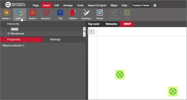
Link button
For the link button to be enabled you must have two and only two valid endpoints selected (see list above). If you have, say, 2 nodes selected and a link, it will be disabled.
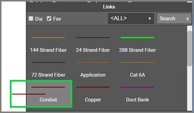
Link catalog pane
4.4.2 Creating links
When the endpoints of a link coexist in the same diagram, the link is called ‘direct’. There are several ways to create direct links between objects.
4.4.2.1 Method 1: select the two endpoints
The first method to create a direct link is to simply select the two endpoints on the diagram and pick a link type from the links sub menu.
The screenshot below shows two nodes selected, and the expanded link menu with several link type options. Upon clicking of the desired link type, an instance of that type is created between the two selected nodes. Just as with nodes, this link type instance will have a set of properties that correspond to the selected type from the link button.
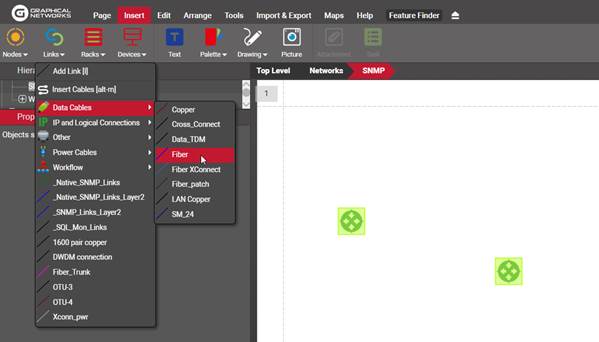
Creating a link between two devices
4.4.2.2 Method 2: Dragging and dropping a link from the catalog
Probably the most straightforward method for creating a link between two objects is to just drag and drop it from the link catalog pane. To do this, follow these steps:
1) Move the mouse to the link catalog pane and select a link type by clicking on the left mouse button
2) Drag the mouse cursor to the starting node on the diagram
3) As you hover the mouse over the starting node, the node should display 9 snapping points (more on that later)
4) Once you identified the desired connection point on the starting node, release the left mouse button and drag the mouse cursor to the endpoint
5) Once you hover the mouse over the ending node, the node should also display 9 snapping points
6) Once you identified the desired connection point on the ending node, press the left mouse button and the link is created!
4.4.2.3 Method 3: using the clipboard
Another way of creating a link is to use the clipboard and multi connection option dialog (more on that later). You can do this, as follows:
1) From the link section of the catalog, select the link type you want to use
2) Select the starting node and copy it to the clipboard (ctrl-c)
3) Click on the end node and then click ctrl-l. Done!
If you want to choose which type of link type you use, during the creation process, an alternative method is the following:
1) Select the starting node and copy it to the clipboard (ctrl-c)
2) Right-click on the end node
3) Select ‘create connection’ (you can use ctrl-l for the shortcut and the last selection for the Multi connection dialog will be remembered, as explained below).
4) The ‘Multi connection’ dialog will open, which lets you choose the link Type you want use. This option is most useful when creating multiple options at once, so for single connections simply pick the link type to use and then next time that setting will be remembered.
5) Click ‘Ok’.
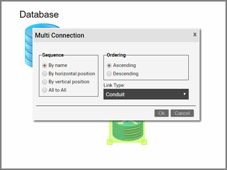
Creating a link using the clipboard and multi connection option
This option is also the one that will be used for creating inter diagram links, as explained later in this guide.
After you used this method for the first time, all the settings above are remembered, in which case the process gets a lot simpler with two easy steps (if you stick with these settings, including the link type):
1) Select the starting node and copy it to the clipboard (ctrl-c)
2) Select the ending node and press [ctrl-l]
4.4.2.4 Method 4: using the ‘l’ key
A very quick way of creating a direct link is by using the ‘l’ key shortcut method, as explained below:
1) With the ‘l’ key pressed move the mouse to the starting node and click on the desired snapping point
2) With the left mouse button pressed (and the ‘l’ key still pressed) move the mouse to the endpoint
3) With the mouse hovering over the endpoint, release the left mouse button when you are over the desired endpoint snapping point and you are done!
4.4.3 Inter diagram links
Links that start and end on different diagrams are called ‘Inter Diagram Links’ and represent a useful way of showing connectivity and relationships between objects residing on different parts of the hierarchy.
Creating an inter diagram link is as easy as creating a direct link using the method 3 described above.
1) From the link section of the catalog, select the link type you want to use
2) Select the starting node and copy it to the clipboard (ctrl-c)
3) Navigate to the diagram where the end node is
4) Select it and then click ctrl-l.
Note that netTerrain will automatically add the corresponding reference nodes to each diagram. These reference nodes will specify on each local diagram, what the corresponding end node on the other diagram is.
The new inter diagram is not only represented on the diagram where it was created. A link representing it, will appear in the following places:
1) On the diagram where each end node exists along with the reference node representing the opposite node. These are also the lowest-level diagrams in the hierarchy where that inter diagram link is represented.
2) On the highest-level diagram where the containing nodes of both end points coexist. In this case the link is a direct link between those two containers.
3) On any intermediate diagram where only one of the containers of one of the end points exists
A user can differentiate a reference node from a regular node by the yellow triangle on the bottom right corner of the node.
Users can also create links by selecting reference nodes. Inter diagram links can be deleted from anywhere in the hierarchy they appear.
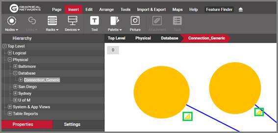
Reference node indicator
4.4.3.1 Bringing in a reference node to the local diagram
If you’d like to bring in a reference node from the remote diagram to the local diagram you are currently in, you could, of course, navigate to the remote diagram, then do some nice cutting and pasting after navigating back to the local diagram. Here’s a nice hack instead:
On the local diagram simply right click on the reference node and click on the ‘Move to this diagram’ option.
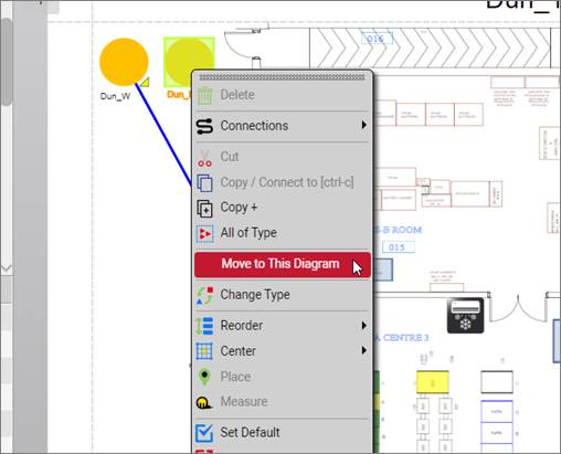
Moving a reference node to the local diagram
4.4.4 Link aesthetics: snapping points, styles and bend points
To help you make your network diagrams look precise, netTerrain supports several aesthetical elements to help you with the task of making your links sing.
4.4.4.1 Snapping points
By default, each link endpoint is connected to the center of the nodes. To provide users with a more granular control on the exact position of link endpoints, nodes in netTerrain have 9 snapping points on a 3x3 grid. They become visible when a user moves the endpoint of a link inside the rectangle that defines the node boundaries.
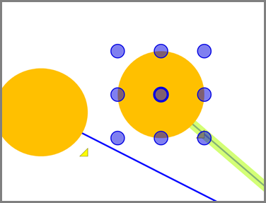
Node snapping points
To make the snapping points visible simply fetch the link endpoint on the node and move it inside the node rectangle by holding the left mouse button. Every time the mouse hovers over a snapping point, it is highlighted so that upon mouse button release, the link is locked to that snapping point. Snapping points are there for convenience only, since a link can be connected to any part of the node, not just the specific snapping points.
4.4.4.2 Link styles
Links can include different line styles, colors and thicknesses, depending on the link type that was defined when creating the instance. These styles are applied for all instances of a given link type, but can be overridden on a per instance basis, using visual overrides. The netTerrain catalog supports the following line styles:
-
Solid
-
Dash
-
Dot
-
Dash-dot
-
Dash-dash-dot
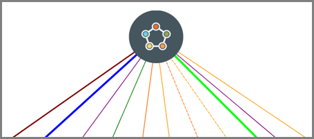
Links displaying different line styles and colors
4.4.5 Bend points
Bend points in netTerrain provide the ability to reroute links within a given diagram. A bend point will partition a link into multiple segments, but they all represent the same original link. By clicking on any segment, the properties for the link will be displayed.
To create a new bend point, select the link and click on the ‘Add Bend point’ button (‘b’ hotkey). Alternatively, you can create a bend point using the bend point button from the Arrange menu.
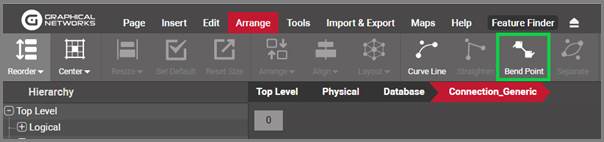
Adding a bend point
To create right-angled bend points, select the bend point and click on the ‘Set right angle’ button (or alt-b). Once the right-angle button has been pressed, the bend point will be positioned at a right angle with respect to its adjacent nodes. The engine automatically determines what the best right-angle option is, based on the relative position of the bend point with respect to its adjacent nodes.
The general rule for this operation is that if the x coordinate of the bend point is closer to the right-most adjacent node, it will be located on the upper right corner of an imaginary right-angled triangle defined by the bend point and its two adjacent nodes.
To delete a bend point, simply select it and click on the delete button or key. If you arrange the bend points or nodes in such a way that an existing bend point no longer “bends” the link, it automatically disappears as it serves no purpose anymore.
4.4.5.1 Creating multiple bend points quickly using the ‘b’ shortcut
A very quick way of adding multiple bend points and directing the path of the link is to use the ‘b’ shortcut. Select the link of interest first and then press and hold ‘b’. Move your mouse to the position of where you want to add a bend point and press the left mouse button. This will add the bend point where you click on the screen. You can perform this operation as many times as you want in succession.
4.4.5.2 Creating right-angled routes for links quickly
Often you may find yourself wanting to create right angled paths for a link between two nodes. For example, you may want to lay out a link so that it looks like a right-angled U. Doing it all manually would require creating two bend points, then moving them appropriately to create a right angle. A much easier way to accomplish this is by using the link ‘right angle’ handle, as shown below.
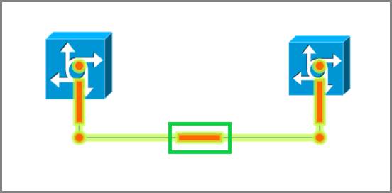
Using the right-angle handle
Just click on the link and then drag that handle until you create the desired U-shape. This feature can be used as many times as needed on any segment of the same link.
4.4.6 Separating links
In many instances two nodes can be connected by several links, which by default would be displayed on top of each other. For each link to be clearly visible, users can quickly accomplish the task of separating the links by selecting them and applying a link separation algorithm.
The process works as follows:
1) Select the links considering that they have to start and end on the same pair of nodes. Also note that since most likely the links will be on top of each other, you may have to select them using a selection box that crosses them at some point
2) Once the links are highlighted, right-click on any of them and click on ‘separate links’, or click on the ‘Separate’ button in the Arrange menu. Note that if that option is not enabled, you may have only selected one link. Make sure you have more than one link selected, and the endpoints are the same
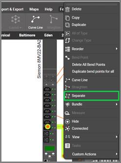
3) With the ‘Separate Links’ dialog open, you can now choose from the following parameters:
a. Separation distance between links (in inches)
b. Number of bend points you want to apply to each link
c. Line curving
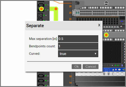
Note that this separation algorithm can be applied to any set of links sharing endpoints, regardless of bend point count, distance between links or curving state.
4.4.7 Creating multiple links at once
netTerrain has several convenient ways for creating multiple links at once. These methods work for any type of link and node.
Where these methods are most helpful is in the creation of multiple connections between ports. For example, let’s connect two ‘patch panel’ devices with links of type ‘Copper’. In case you are not familiar with these types of devices, just imagine them as nodes with an ordered set of sub nodes underneath.
Let’s say we wanted to create 6 cable connections between ports 1 to 6 on patch panel A and ports 1 to 6 on patch panel B. These are the typical steps to accomplish that task:
1) Go into the patch panel A diagram and select the 6 starting ports
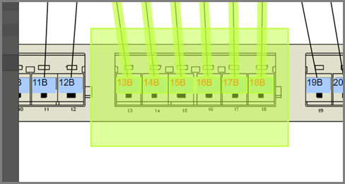
2) Copy all ports to the clipboard (ctrl-c)
3) Go into the patch panel B diagram and select the 6 ending ports
4) With those ports selected, right-click and select ‘Connections’ -> ‘Create’
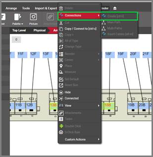
5) A ‘Multi connection’ dialog pops up, where you can select the type of sequence, ordering and catalog link type and click ‘Ok’
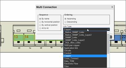
After clicking ok, 6 cables are created, with their corresponding reference nodes and interdiagram links.
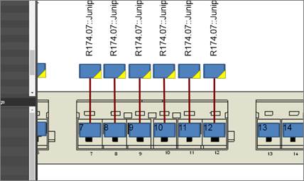
6 cables added via the multi connection option
The sequence options provide a great degree of control for choosing which starting nodes are connected to which ending nodes.
4.4.8 Easy cable management using the cable mapper
Cable management can be a daunting task, especially if you need to create many cables between different ports in your inventory. You can use shortcuts and other methods to create single cables between different ports. You can also create multiple cables between sequences of ports using shortcuts, however this only works when there is some sort of uniform pattern for the connections. In addition, for these techniques you always need to go to the actual ports to start the connection process. Enter the “cable mapper”.
The cable mapper is an informal name that we use for a utility launched from a context menu, which already existed in the Integration Toolkit (ITK) in an unofficial capacity to speed up the process of creating cables. We ported this utility to the web-based interface, improved it and made it official. It can be used for any kind of link connection, but we refer to it as the cable mapper because the endpoints are always ports and the way you create the cables is by mapping these port endpoints, as we will see below.
The cable mapper simplifies the process of creating cables in two ways: you can launch it from anywhere in the project by selecting two nodes and it doesn’t require a specific connectivity pattern for cables to be created.
You launch the cable mapper utility by selecting two nodes from a diagram. As mentioned above, they don’t have to be the actual ports or even the devices that you want to connect. It can be the two buildings where the end devices are. This is quite convenient because right there it already simplifies the process by not having to navigate to the endpoints back and forth. After selecting the two objects bring up the context menu (alt-c) and click on the “Insert Cables” menu. Or just click on alt-m, which is the hotkey for the utility.
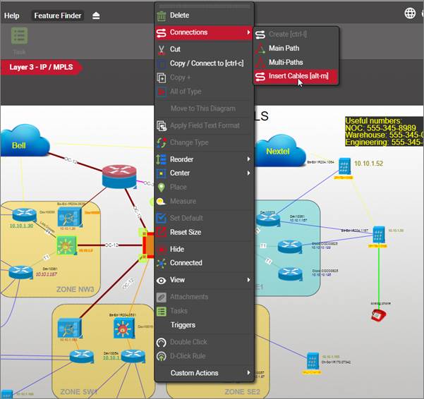
Insert Cables utility launched for two buildings
The cable mapper shows you the two endpoints, and their entire hierarchy, as well as a list of already existing cables between these two endpoints on the far-right window. You can navigate both hierarchies until you find the devices you want to connect. You can expand the devices to show the ports. If the devices have cards, you can expand those as well.
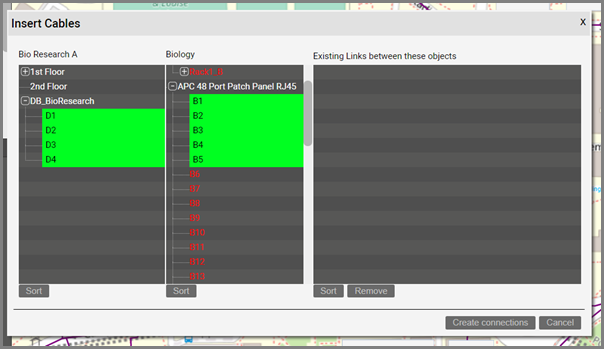
The cable mapper interface
At this point you can start clicking on the ports you want to connect on each side. You can use the ctrl or shift keys to multi-select ports. Two sort buttons let you sort the ports in ascending or descending order on each side.
Once you are done selecting the ports you want to connect, you press the ‘Create connection’ button. This opens a dialog that lets you choose the sequence in which you want to connect these ports and the ordering.
Sequence:
-
By name: connects port 1 with 1, 2 with 2, etc.
-
By horizontal position: connects the left most port with the left most, and so on
-
By vertical position: connects the top most port with the top most, and so on
-
All to All: connects every port on the left with every port on the right
Ordering:
-
Ascending: connects ports in ascending order (such as if, for example, you choose the ‘By name’ option above, you are now connecting the ports front-to-back)
-
Descending
Link Type: lets you choose which catalog type you want to use for these cables
Once you click ‘Ok’ the connections are created.
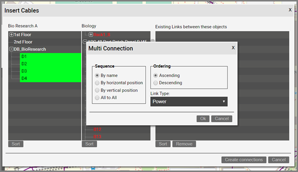
Creating cables with the cable mapper
The cable mapper will remember the settings for the multi-connection dialog above, so that next time you use the same preferences, you can just click through it.
By being able to click through this dialog, you are also making it easy to quickly create connections between ports in no discernible pattern. Just select any pair of ports from the cable mapper, create the connection, and click through the dialog.
Because the cable mapper shows you existing connections between the selected endpoints, it can also be used to quickly remove existing connections. Just select any connections from the right panel and click on the remove button.
4.5 Free text, palette objects, drawings and pictures
As we saw briefly in the chapter reviewing the GUI, users with annotation rights (or better) can insert a series of elements that although are not part of what you would consider the project inventory (nodes, links, devices, etc.) can come in handy to decorate a diagram or provide information related to the project. These elements include free text, palette objects, drawings and pictures.
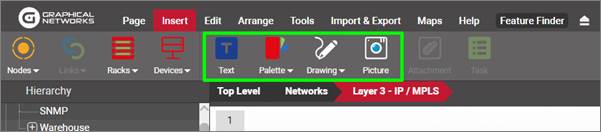
Free text, palette object, drawing and picture menus
4.5.1 Free text
Users with annotation rights (or better) can insert free text in any netTerrain diagram by clicking on the text button under the Insert ribbon, as depicted below.
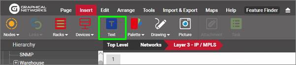
Inserting free text
Once you press the Text button, a free text dialog pops up, which includes many options to format your text appropriately. Formatting options include:
- Bold text
- Italics
- Underline
- Font type
- Font size
- Font color
- Fill color
- Expression insertion
We will cover expressions in more detail later in this guide.
Attention!
In addition to free text, netTerrain also supports the display of property values on a diagram (called displayed fields). As opposed to displayed fields, free text is not associated to any node or link on a diagram. We will cover displayed fields later throughout the guide.
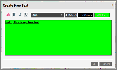
Free text dialog
4.5.2 Palette objects
Users with annotation rights, or higher, can also add and remove palette objects. These objects represent an additional layer of information on top of the netTerrain network schema. Annotators can only insert new palette objects, or update and delete their own. Editors or higher, can edit or delete annotations that were created by any user.
Palette objects come in 4 types:
- Comments
- Documents
- Shapes
- Stamps
All palette objects support custom fields and all attributes are searchable within the netTerrain database.
To add a palette object node, a user can click on the palette button, or simply right-click on the diagram and click on the appropriate palette option. Once added, palette objects can be edited just like regular nodes.
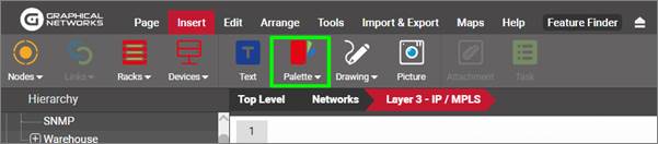
Palette object menu
To remove a palette object simply select it and then click on the ‘Delete Object’ button (or ‘del’ key).
4.5.2.1 Comments and stamps
Comments are generally used to decorate a diagram with pertinent information about pending changes or edits needed to improve it. Comments already have a comment field and use an image based on an orange pointy geometric figure, as displayed below.
Stamps offer users a limited set of predefined labels, usually reserved for marking the status of the current diagram. The image above shows the submenu with the available stamps.
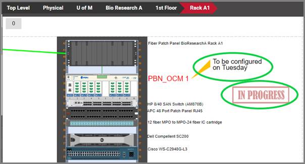
A comment and a stamp on a diagram
4.5.2.2 Documents
A document node in netTerrain can be useful for serving as a pointer to an actual document by assigning a hyperlink to the Document ‘path’ field. This behavior is not exclusive to documents, since, as is explained above, any node in netTerrain can have a field value with a hyperlink embedded in it. The convenience lies in the fact that document nodes already use an icon that looks like a document and already include a predefined field called ‘path’.
For a document node to be able to open the actual document, the following is required:
- The document must be accessible via a URL, and the server needs to reach that address
- The application that opens the document needs to be installed on the client machine
- The URL must be preceded by http:// or https://.
The path for the document object conforms to the same construction rules for hyperlinks as any other fields. An example of a valid hyperlink path is the following:
Once the document has been added with the hyperlink, the node and path fields will look as follows:
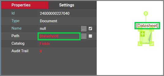
Document node with hyperlinked path
Attention!
Notice that starting with version 5.4, netTerrain included a document embedding feature (akin to SharePoint), which is usually better suited for the task of sharing documents and files (see chapter on change management). If you need controlling the flow of documentation or you want to use netTerrain as a document repository, we recommend using that feature instead. We do keep these document nodes mainly for backwards compatibility reasons.
4.5.2.3 Shapes
Shapes are special palette objects that support vector background colors and line styles, as well as transparency levels. Shapes can be used for several purposes:
- to delimit boundaries between inventory objects
- to create grouping objects to place inventory items inside
- as placeholders for actual object that need not be inventoried
- to enhance a diagram with indicators using geometrical figures
Shapes are vector objects that include four special features in the settings tab, by which the user can choose a color, transparency level, a shape type and a line style and thickness.
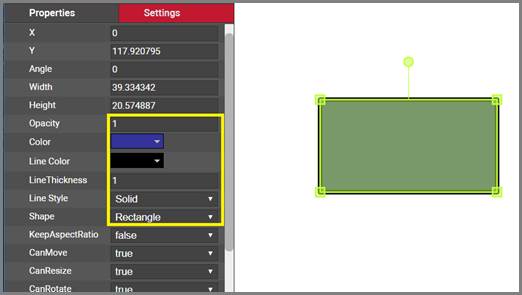
Shape settings
The following shape types are currently supported in netTerrain:
- Rectangle
- Rounded rectangle
- Triangle
- Right triangle
- Pentagon
- Hexagon
- Octagon
- Five-point star
- Seven-point star
- Parallelogram
- Cross
- Cylinder
- Chevron
- Ellipse
- Donut
- Arrow
- Double arrow
- Diamond
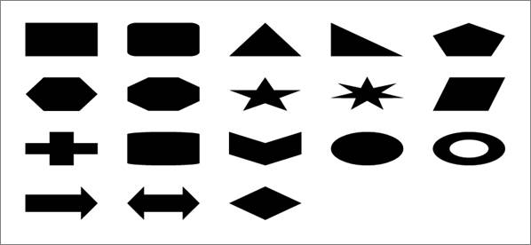
netTerrain Shapes
4.5.3 Drawings
netTerrain let's you create three types of free drawings to enhance the look and feel of your diagrams. These include:
- Lines: single lines that do not require two nodes as end points
- Paths: a collection of consecutive segments
- Polygons
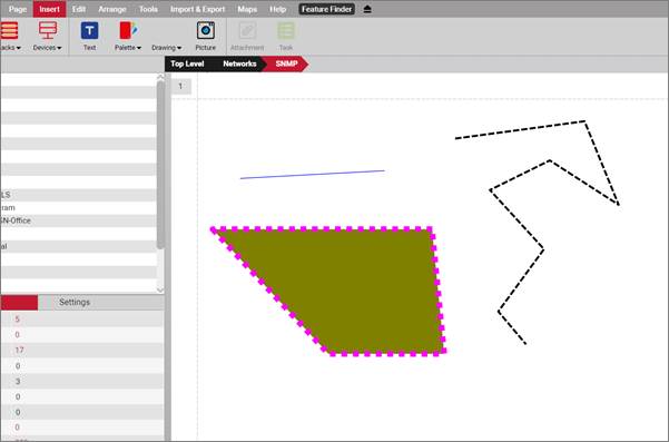
Lines, paths and polygons
4.5.3.1 Lines
To create a line, follow these steps:
- Click on the line sub menu
- Hold the left mouse button where you want to start the line
- Drag the mouse to where you want the line to end
- Release the left mouse button
By holding the ctrl key, the line will snap at 15-degree angle increments. This is especially useful when you need the line to be exactly at, say zero or 90 degrees without having to control your pulse that hard.
4.5.3.2 Paths
To create a path, follow these steps:
- Click on the path sub menu
- Hold the left mouse button where you want to start the path
- Drag the mouse to where you want the next segment to start
- Release the mouse to start the second segment
- Keep dragging and clicking on the left-mouse button as many times as segments you want
- Double-click to finish the path
By holding the ctrl key, the path segments will snap at 15-degree angle increments.
4.5.3.3 Polygons
To create a polygon, follow these steps:
- Click on the polygon sub menu
- Hold the left mouse button where you want to start the polygon
- Drag the mouse to where you want the next side to start
- Release the mouse to start the second side
- Keep dragging and clicking on the left-mouse button as many times as sides you want for the polygon
- Double-click to finish the polygon
By holding the ctrl key, the polygon sides will snap at 15-degree angle increments.
4.5.4 Pictures
In addition to background images (which are fixed to the diagram), users can upload pictures as well. Pictures can have custom fields and are searchable, but just as other palette objects, it is not possible to link them or double-click on them.
To upload a picture, open the ‘Insert’ menu ribbon and click on the button that looks like a camera, or right-click on the diagram and select ‘Insert picture’.
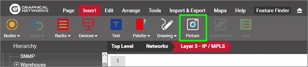
Uploading a picture
4.5.4.1 Adding a picture by dragging and dropping
Just as with nodes, there is a nice trick to add a picture into the project quickly: by dragging and dropping an image from a folder or browser!
The best way to use this trick is to have both the netTerrain browser and the folder or website with the image side-by-side. Then, just drag and drop the desired image to the netTerrain diagram, as shown below:

Create a picture by dragging and dropping an image
After you dropped the image on the diagram, netTerrain gives you the option to create it as a floating image (picture), a node type, a device type, or a rack type. Choose the ‘Picture’ option:
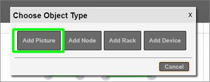
Choosing the ‘Picture’ option to create a floating image
This completes the process!
Tip:
You can also perform the same operation by simply copying a picture from your computer with ctrl-c and then pasting it on the netTerrain diagram.
5 Advanced features
5.1 Hiding and filtering information
Users can filter out objects in a diagram, either by hiding individual nodes or by applying diagram filters. Except for the ‘Show connected’ option, these filters are persistent, meaning that the changes will stay after the session has ended, and will be visible to all users.
5.1.1 Hiding individual nodes
To hide a node or group of nodes, simply right-click on them and click on the ‘Hide’ sub menu.
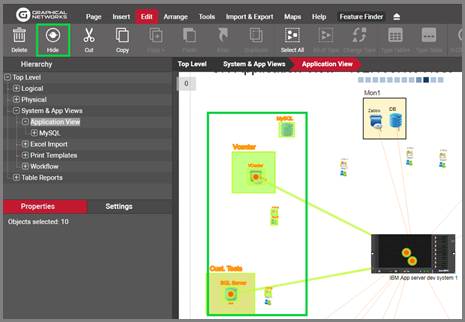
Hiding nodes
Any hidden node will also hide any connecting link, and if a diagram has hidden nodes, the diagram properties will show a ‘Hidden nodes’ counter.
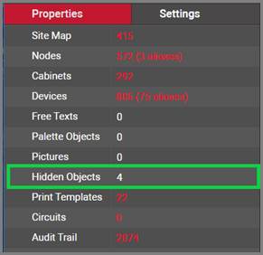
Hidden nodes counter
To show all hidden nodes, simply right-click on the diagram and select ‘Show hidden nodes’ (or the hotkey shift-a).
5.1.2 Temporary filters: hiding unconnected objects
In many cases it is useful to see what’s connected to a specific node or group of nodes. netTerrain includes a convenient temporary filter (per user) that shows “what’s connected”.
To hide everything that is not connected to a node or group of nodes, select the set of nodes you want to isolate and then do one of the following:
1) Click on the ‘Connected’ button in the Tools menu
2) Right click on the selection and press ‘Connected’.
3) Or our favorite: press the ‘Shift-h’ hotkey!
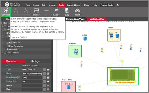
Using the ‘Show connected’ option
After you hide all unconnected objects, the hidden objects counter (see below) will be increased by the number of objects that are now hidden.
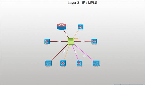
Result of a ‘Show connected’ action
To see all unconnected objects again, you can bring up the diagram context menu and click on the ‘Unhide all’ option (or [shift-a]).
Attention!
Be careful using this option though, because this will indeed unhide all objects, even previously hidden ones. A better option for reverting the ‘Show connected’ option is to use the ‘Esc’ key. Not only is this faster to do, but it will also preserve the hidden state of any objects previously hidden. This is also why we refer to this filter as a temporary filter, since it is client-side and not persistent.
Tip:
Use your shortcuts! Press [shift-c] to apply the filter, it is much faster than right-clicking and selecting the menu option.
5.1.2.1 Using filters with links
You can also use these filters with links. For example, you may select a link, set of links or a full path, as shown below.
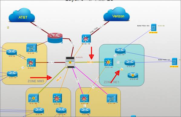
A path with three selected links before applying the filter
After pressing [shift-c] all objects on the diagram except that ones that serve as endpoints for any of the selected links will be hidden.
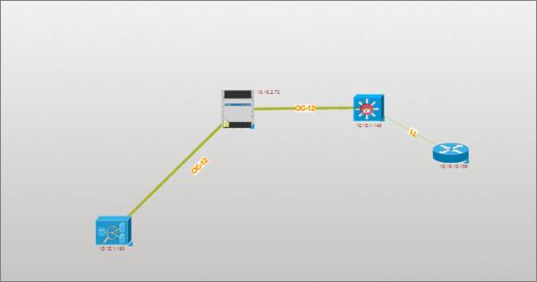
The selected path after applying the filter
Tip:
If you want to select a path, you can click on one link and use the shortcuts [shift-q] and [shift-w] to auto select links upstream or downstream along the path.
5.1.3 Viewing hidden objects in outline mode
In addition to the ‘Hidden Objects’ indicator in the properties window, netTerrain also displays a hidden objects counter on the top right corner of your diagram. When hovering the mouse over this counter, netTerrain briefly displays objects in grayed out (or outline) mode. The objects will immediately disapppear once you move the mouse pointer away from the counter.
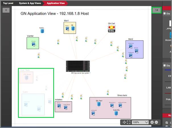
Hidden objects in outline mode
5.2 Layers
Layers in netTerrain are per-diagram filters that operate over an entire type or category of objects whereas the process of hiding or filtering, as reviewed in the previous section, operates on individual instances.
Layers come in four flavors:
- Node layers
- Link layers
- Field layers
- Miscellaneous layers
The layers pane can be enabled from the page menu or by simply pressing ‘F4’.
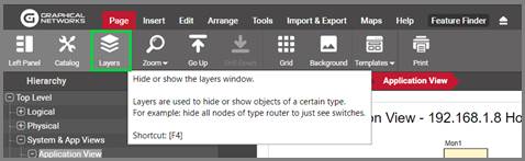
Showing the Layers pane
Just like with the catalog pane, the layers can be docked on the bottom right part of the page or can be floating.
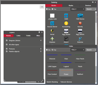
Floating layers pane
5.2.1 Node layers
Node layers are per-diagram filters for nodes that let you quickly hide or show instances on a per node type basis.
The node layers feature automatically lists all distinct node types that exist on the diagram. A checkbox displayed in the layers ‘Nodes’ tab, in front of each type, lets you hide or show all instances on that particular diagram for that specific type.
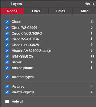
Node layers tab
A counter next to each type tells you how many instances of that type you have on the diagram.
If you uncheck any of the types, these objects are hidden from the rest of the objects on that diagram. This setting applies to all users and is persistent throughout browsing sessions.
The screenshot below shows the cloud object type being hidden from the rest of the diagram. When hovering the mouse over the hidden counter, those clouds are displayed in outline mode.
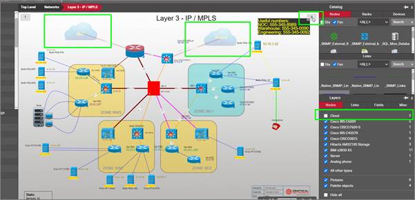
Using the node layering feature
Notice the option ‘All other types’ how below the discovered types you find an. When this option is checked, if an instance of a new type is added, it will be shown by default, otherwise it will be hidden.
Also notice the last option, 'Hide All', which when checked, unchecks every other type from the filter and essentially hides all objects from the diagram.
Attention!
The Node Layers pane also features two system object classes that can be turned on or off on the diagram: the pictures and the palette objects.
5.2.2 Link layers
Link layers are per-diagram filters for links that let you quickly hide or show instances on a per link type basis.
The link layers feature automatically lists all distinct link types that exist on the diagram. A checkbox displayed in the layers ‘Links’ tab, in front of each type, lets you hide or show all instances on that particular diagram for that specific type.
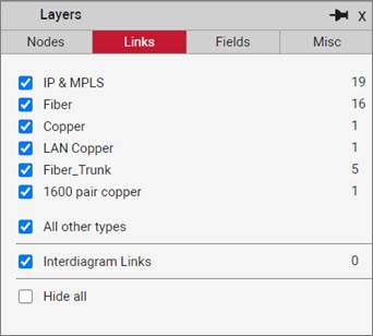
Link layers tab
A counter next to each type tells you how many instances of that type you have on the diagram.
If you uncheck any of the types, these objects are hidden from the rest of the objects on that diagram. This setting applies to all users and is persistent throughout browsing sessions.
Notice the option ‘All other types’ how below the discovered types you find an. When this option is checked, if an instance of a new type is added, it will be shown by default, otherwise it will be hidden.
Finally, you can choose to hide all links on the diagram by checking the ‘Hide all’ checkbox at the very bottom of the tab.
Attention!
The Link Layers pane also features the inter diagram links as a separate class of links that can be turned on or off on the diagram.
A good use case for link layers is in a floor plan view. For instance, you may want to see trays (modeled as links), but not each individual cable. The example below shows a floorplan view with tray section running in the middle of the diagram. These trays are modeled as links and fiber and copper cables are associated with those trays. The display filter prevents any new copper or fiber strands to be displayed when they are added to the diagram, or any object underneath.
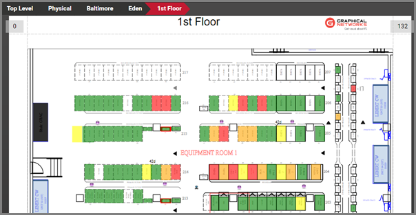
Floor plan view with trays modeled as links and other connections filtered out in layers
In addition to working with diagram displays, users can still hide individual objects (reviewed later in this guide). Any objects that were explicitly hidden will not be affected by the diagram displays. This means that if a specific link is hidden, and later the ‘Links display’ option is utilized by hiding all links of the same type as the hidden one, the original link will still remain hidden even after you disable the filter.
5.2.3 Field layers
The field layers pane lets you turn all node and link displayed fields on or off. Notice that when you turn off node fields, it also turns off any palette object displayed fields.
Below we you two screenshots, one with all node (and palette object) displayed fields turned on and the second screenshot showing them off.
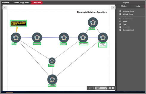
Node displayed fields turned on
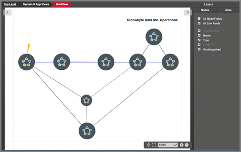
Node displayed fields turned off
In addition, this feature lets you turn any particular tagged properties on or off. Tags will be reviewed in the next section.
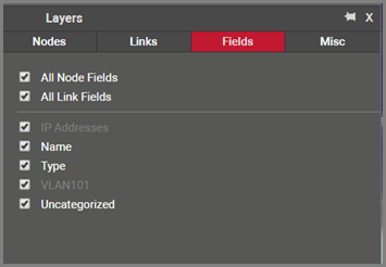
Field layers paned
5.2.4 Field tags
Field (or property) tags allow you to associate fields to a “tag” (i.e. layer). All existing tags appear in the fields tab in the layers pane. Fields associated with a tag label can be turned on and off within a diagram. So, you could assign a field like IP Address to an “IP address fields” tag. If you happen to be on a diagram that has objects containing that field, you could then turn all IP Address fields on or off without having to individually uncheck them from the properties window for each instance.
Tags are set up and mapped to properties by a power user (see Power User Guide).
The screenshot below shows different layers that were defined in the catalog. A simple click on the checkbox next to the ‘IP’ layer will hide all IP addresses (green displayed fields on the diagram).
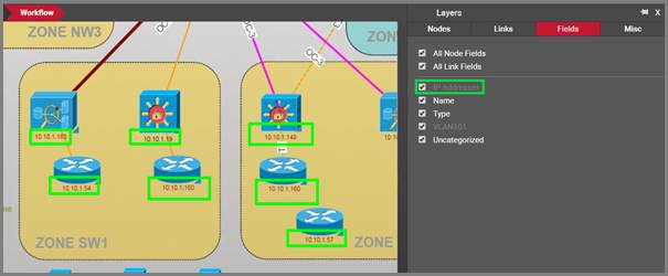
Field layering feature
5.2.5 Misc layers
The Miscellaneous (‘Misc’) layer groups other layers or classes of entities that can be turned on or off. These include
- Free text
- Background
- Margins
- Rack lines
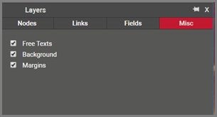
'Misc' layer
As you may suspect, the Rack lines only apply to rack diagrams.
5.3 Table views
An alternative view to diagrams in netTerrain is the table view. A table view is a display of data in a column and row representation. netTerrain includes a predefined set of table views that can be accessed from different parts of the hierarchy. Customers can also create their own table views (see Database and scripting guide).
Table views are typically accessed from the properties window, in the form of a URL link that summarizes the underlying data. There are other ways to access table views, though. The view menu lets you choose from several options to display objects in tble:
- Type Table+: view all instances of a certain type for the whole project
- Type Table: view all instances of a certain type for the current diagram
- Type Table with visible only: view all instances of a certain type that are visible on the current diagram
- Table with Selected: view a table of the selected objects (only valid if the selected objects are of the same type)
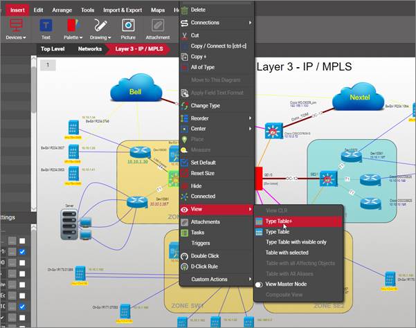
Viewing instances of a type in table view
Diagrams also contain built-in table view that can be accessed from the properties tab. The top-level network view, for example, has a summary of its contents, such as the site map, nodes, devices and links that are contained in the project.
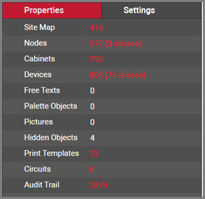
Properties window displaying hyperlinks to underlying table views
Clicking on any of the links that summarize data will take the user to the corresponding table view.
5.3.1 Hybrid vs type-specific table views
Table views come in two flavors: hybrid and type-specific.
Whether a table is one or the other is determined automatically by netTerrain based on context.
When a user invokes a table from the properties window, as explained above, then the data can contain instances from different types. Because every type has a different set of properties, netTerrain cannot show custom properties in that table. Instead, it shows common fields for all types, such us the Id, name, type and ancestry.
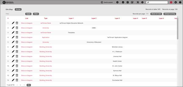
A hybrid table view showing the site map
When a user launches a table from the right-click context menu using one of the ‘Table with all of Type...’ variants, then all instances are of the same type, in which case the table view will show all custom fields for those instances.
5.3.2 Editing data from a table view
Using the same reasoning explained above, it is easy to see that a hybrid table cannot be edited directly from the table, since custom fields are not represented. In that case, table views show an ‘Edit’ link for each record, which opens the record editor:
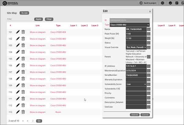
Editing a record from the table view
A type-specific table, on the other hand, has no edit field link since the data can be edited directly on the table.
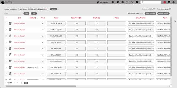
Type-specific table view showing editable textboxes for each record
Each record in this table view has an editable textbox (or combo box) for each custom property. This has the added convenience of being able to quickly navigate through cells using the arrow keys.
Notice that both variants of tables support the delete features. Deleting records from a table view is essentially the same as deleting them from a diagram.
Attention!
Calculated or system fields are not editable, and aliases have no editable fields at all. To change the values for an alias you must go to the master instance and edit custom properties there.
5.3.3 Navigating from a table view to a diagram
In most cases, a link to the diagram that contains the object will also be displayed next to the edit and delete buttons.
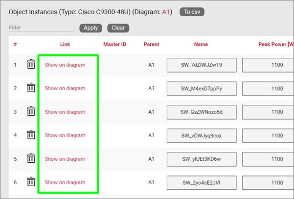
Show on diagram link
By pressing this link, users are taken to the diagram that contains the object and the object will blink.
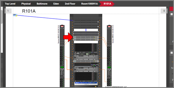
Navigating from a table view to the diagram
5.3.4 Other table view features
Table views include several additional standard features, which are mostly self-explanatory:
5.3.4.1 Column sorting
All name and custom fields are sortable in a table view. Press on the column header once for ascending order sorting and press again for descending order sorting.
To go back to the default sorting, click on the ‘default sorting’ button:
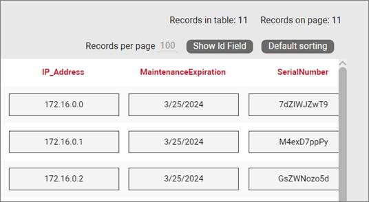
Default sorting
5.3.4.2 Hiding and showing the id field
By default, table views will not show the instance id column, which can be shown by pressing the ‘Show id field’ button on the top right corner. The id column can be a useful feature to find out which records were added most recently. Since every record has a unique id and ids are issued sequentially in ascending order and never reused, to find out which records are newer click on ‘Show Id field’ then press on the Id column header (and make sure the arrow next to the header is pointing down) and voila! Your records are sorted by most recent in descending order.
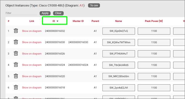
Sorting records by most recent in descending order
5.3.4.3 Pagination and counters
The top right corner of the table view will display how many records are displayed per page and how many records exist in total. The records per page counter is editable on the table view and the default records per page is a setting that can be changed in the admin console by an administrator (see Admin guide).
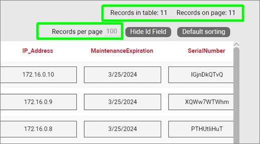
Record counters
As you would expect from a table view, pagination is supported and available at the bottom of the page. The pagination features are self explanatory, methinks!
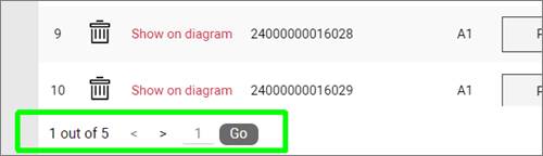
Pagination in table views
5.3.4.4 Exporting table views to csv
All table views can be exported to csv. The export will include all the columns that are displayed in the table view. To export, simply click on the ‘Export to csv’ button on top. Once clicked, the user will be prompted to open or save the file to disk.
The method to retrieve the generated csv will depend on the browser used. The screenshot below shows the place to fetch the csv when launched from a Chrome browser.
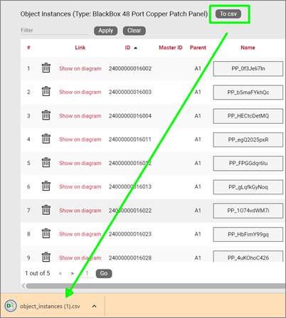
Exporting to csv
Tip:
Csv formats can be opened with spreadsheet software like Microsoft Excel. You can then take advantage of the features in those tools to further manipulate the information or create reports.
5.4 Queries
Besides running a search, which retrieves results as a table, or running a pre-defined table view report, an end-user can also design a simple query, run it and store it, all through a simple-to-use GUI.
To create queries dynamically, follow these steps:
1) From the Tools menu click on the ‘query’ button, which opens a ‘Create Query’ dialog. We recommend you name the query so you can retrieve it later.
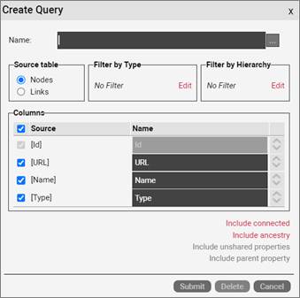
2) In the create query dialog pick the source table (nodes or links).
3) If you want to filter by type click on the ‘Edit’ link in the Filter by Type section.
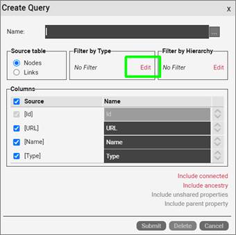
4) The filter by type option let’s you browse types by current diagram and/or below (which limits the types a lot and makes them easier to find), and also let’s you pick one or more groups, or choose one or more types from a specific group.
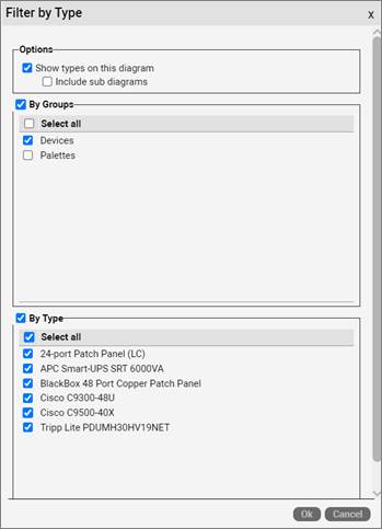
5) The filter by hierarchy option let’s you limit the table results by the current diagram or the whole ancestry.
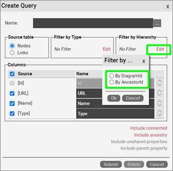
6) In the columns section you can pick which fields should be included in the table view results. In the case of multiple types, the default is that only common fields to all types are included. You can include specific fields not shared by all types by clicking on the ‘Include unshared properties’. You can also check or uncheck any specific fields from the columns section to modify the result set.
7) Finally, you can also include nodes connected to the nodes in the result set, as well as the ancestry for each node:
a. The include connected option let’s you pick which group types of objects should be displayed for the connected recordset and specify where that information should be inserted in the report.
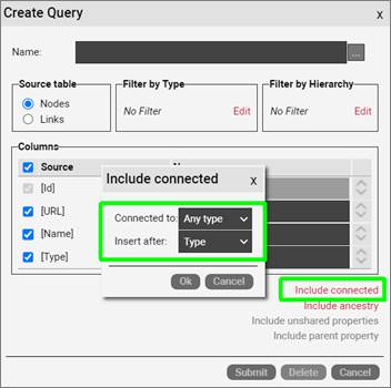
b. The Include ancestry option let’s you pick if you are displaying ancestors by level, in which case you can also choose how many levels of ancestors should be included in the report as well as the ordering, or by type, in which case you pick one type to act as the query clause. You can also specify where in the column order this information should be inserted. Notice that if the include connected option was enabled, the include ancestry feature also gives you the option to append the ancestry information for the connected objects.
8) After you selected all your options and click on the ‘submit’ button of the query dialog a table view is launched in a separate browser tab. This is your table view!
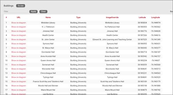
Retrieved table view
5.4.1 Loading an existing query
Of course, you don’t want to have to go through all these options every time you run the same table view. Thankfully, netTerrain saves your queries automatically, after you named them during your original query design process. To retrieve a query, simply open the create query dialog, and load up your query using the ‘Load an existing query’ option (ellipsis button).
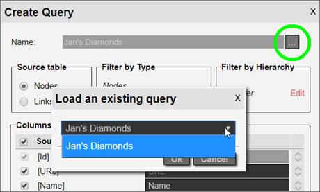
Loading an existing query
After you loaded the query, you can then edit it, or simply run it again.
5.5 Diagram templates
In some cases, users may want to apply a standard layout to several diagrams without having to create the static objects (free drawings, background, text, etc.) that comprise each diagram manually every time. To do that, users can set up any given network diagram as a template and then apply that template to any other network diagram.
If a diagram has been defined as a template and then another diagram applies that template, the template background image and all its shapes and shape displayed fields will also appear on the template consumer (that diagram).
To set up a diagram as a template, simply go to the diagram, right-click on the empty space of the diagram and use the ‘Set as Template’ submenu or use the ‘Template’ button from the Page menu.
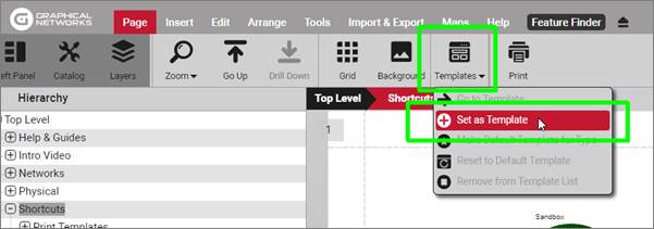
Setting a diagram as template
If the set as template option is not enabled it could be because the diagram itself is using a template. A diagram cannot serve as a template and at the same time use another diagram as a template.
To apply a template to a diagram, simply go to the diagram, click on the settings tab and seelct from the list of available templates.
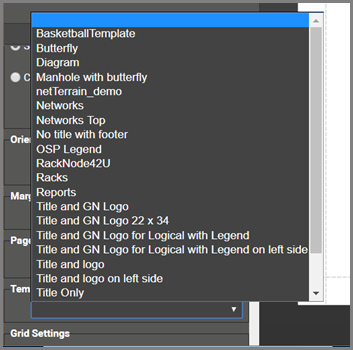
Applying a template to a diagram
The drop down list that you see for the templates lists all diagrams in the project (by name) that have been set as a template.
Attention!
You cannot set a diagram as a template if it is currently using another template. You must first remove the template from the diagram, as explained below.
5.5.1 Removing the template for a diagram
To remove the template from a diagram, follow the same steps as if you were applying a template to the diagram and select the empty record (as shown above).
5.6 Advanced link features
5.6.1 Circuit Layout Records
Circuit Layout Records (CLRs) are end-to-end views of a path between two nodes represented in one single diagram. For example, I may have a desktop computer connected to the internet router via a wall jack, patch panels and a switch. A CLR displays that entire path in one diagram.
The rules for CLR generation are the following:
1) The starting node must have a connection to some other intermediate node (hop) or end node.
2) Each hop needs to have one connection to the next hop.
3) The CLR stops until a node has no more connections to a next hop, or more than one outgoing connection. In other words, the CLR is generated for paths that are unique.
Attention!
If you double-click on any link along the path netTerrain will redirect you to the diagram containing that link and make it blink.
CLRs are not explicitly constructed. They are automatically generated by virtue of nodes being connected with each other. To visualize a CLR do one of the following:
1) Double-click on the link for which you want to see the CLR
2) right-click on a node along the potential CLR path and select the View-> View CLR option.
3) Right-click on a link and select the CLR option
4) Click on the CLR button under the ‘Tools’ menu
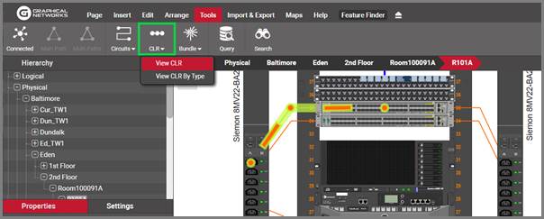
Visualizing a CLR
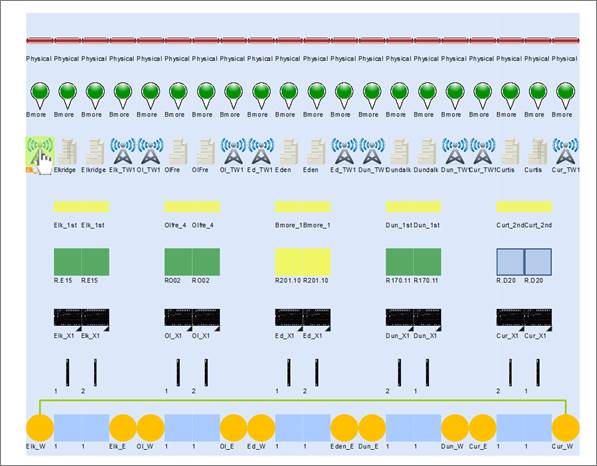
CLR view
The image above shows a CLR for an antenna (on the left) connected to another antenna (on the right), with all the hops in between. Users can double-click on any node on the CLR and jump to the diagram that contains that node.
Tip:
If you double-click on any link along the path netTerrain will redirect you to the diagram containing that link and make it blink.
5.6.1.1 Running a CLR by type
In some cases, you are interested in the CLR for a given link type only. netTerrain can launch a CLR by type with the extra advantage that it ignores any other connections that are not of the same type as the connection type that triggers the CLR. If multiple paths exist, but all the alternative paths are of a different type, those will be ignored. This is the only case where rule 3 (above) does not apply.
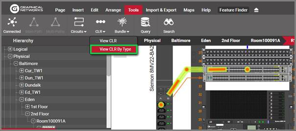
CLR by type option
5.6.2 Main (or shortest) paths
netTerrain can find the shortest main and secondary paths between two nodes on the same diagram. This feature has two limitations:
- Only works for two nodes on the same diagram
- The connections have to be at the diagram level (and not bubbled up from diagrams underneath)
To find the main path between two nodes, select two (and only two) nodes and right-click on one of them (or press alt-c). You can also click on the ‘Main path’ button under the tools menu, as shown below:
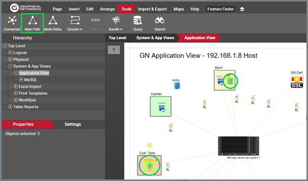
Shortest path option
Alternatively, you can select both nodes and press [shift-p] for the shortcut.
netTerrain, after finding the shortest path, will highlight that path:
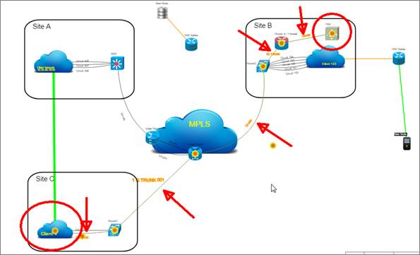
Shortest path between two nodes
The ensuing path can be easily isolated from the rest of the diagram by simply pressing [shift-c], which only shows the node endpoints for each segment of the path:
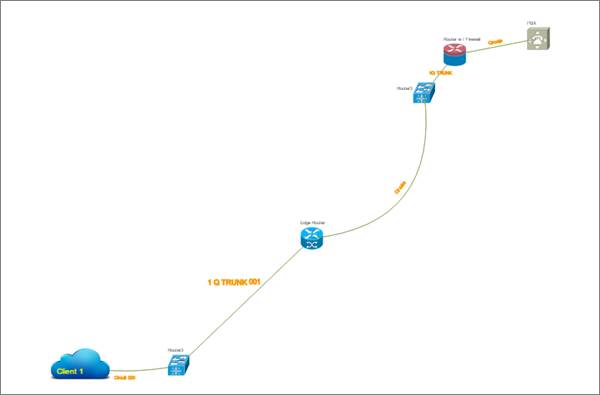
Isolated shortest path between two nodes
When requesting the main and secondary paths netTerrain will find the shortest path first, remember all the intermediate nodes on that path and look for the shortest alternative path that does not pass through any of those remembered nodes.
If a main and secondary path exists, then they will be highlighted as well, and can be isolated just as described above.
If no main path exists, or, in the case of requesting the main and secondary paths, no two paths exist, netTerrain throws an error:
No open paths found
5.6.3 Link bundles
netTerrain can represent parent to child relationships with nodes in a natural way by double-clicking on the parent node and accessing the child nodes on the sub diagram. With links a somewhat similar representation is also possible: the ability to associate several links with a “higher order” link. Moreover, this association can be done across an infinite number of layers and hierarchies.
This feature is called link bundling and some of the ways you can take advantage of this feature include:
-
bundling copper and fiber cables to trays (where the tray is the higher level ‘link’)
-
bundling fiber strands to fiber trunks and fiber trunks
-
bundling SONET or SDH circuits with their higher-level containers
There is no restriction on which types of links can be bundled and the bundling is also possible in a “many-to-many” relationship fashion. Multiple lower level links can be associated with one or more higher level links.
To create a link bundle, follow these easy steps:
1) Select the lower level links
2) Copy them to the clipboard (ctrl-c)
3) Select the higher-level links
4) Right-click on any of them (making sure they all stay selected)
5) Click on the option ‘bundle’ or click on the ‘Bundle’ button under the tools menu
6) Select the ‘Bundle with copied links’ option
As an example, we can select multiple copper cables in a data center, copy them to the clipboard and then select several tray sections, and bundle the copper to the trays.
A particularly useful case for link bundling is the representation of fiber strands at high level maps. You wouldn’t want to have all fiber strands displayed on a map, instead you just want to see the fiber trunks or conduits, but you may still want to click on a trunk or conduit to get a report of all the bundled strands.
To do this:
1) select, say, 4 fiber strands from a diagram and copy them to the clipboard
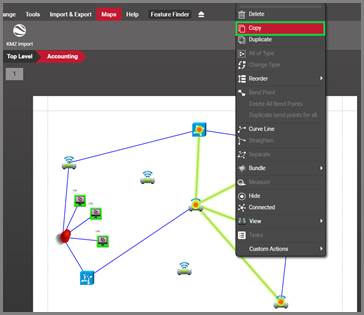
2) Select the fiber trunk path, as depicted below
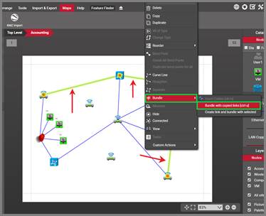
3) Click on ‘Bundle’ -> ‘Bundle with copied links’
4) As a final step you can then hide the 4 fiber strands from the diagram, which will improve the visibility of the diagram while still providing a way to see which strands are associated with which trunks.
You can also bundle a link with another one directly from a CLR view, by right-clicking on any link in your CLR view:
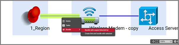
Bundling from a CLR view
Once we created our bundle, users can later on see which lower level links are associated with the higher level links and viceversa.
To find all the links bundled with another link, simply click on the link and click on the bundled links hyperlink in the properties window.
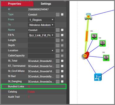
Getting a report of bundled links
This hyperlink will open a table report of all the links bundled within the higher level link. This report includes the link names, types, ids as well as ancestry (2 levels).
From that report a user can remove individual links from the bundle by clicking on the ‘unbundle’ button or click on the ‘show on diagram’ option for any particular link and go to the starting point of that link (usually in a lower level diagram, such as a device backplane).
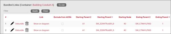
Bundled links report
Given a link that has been bundled inside higher-level links, it is also possible to get a report of those ‘parent links’ by simply clicking on the link and then clicking on the ‘Containers’ hyperlink.
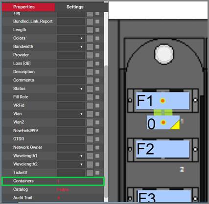
Obtaining the 'container' links for a lower level link
5.6.4 Link measurements
Diagrams with embedded coordinates can be used to measure link lengths. Simply right-click on a link to open the context menu and select the option ‘Measure’. Alternatively, you can click on the ‘Measure’ button available in the Maps menu.
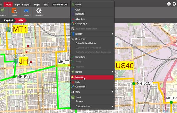
Link Measurements
5.7 Embedding coordinates in a diagram
This feature explains the process of embedding coordinates in static background images. For the GIS (georeferenced) maps please refer to the Outside Plant module chapter.
Backgrounds in netTerrain can contain coordinates, which can be useful in several scenarios. Some of the uses for embedded coordinates include:
-
GIS awareness of a map using latitude and longitude coordinates
-
Creation of custom coordinates for measurement purposes using a variety of coordinate systems
-
Automatic positioning of objects using the Integration Toolkit
Strictly speaking, the coordinates are embedded in the diagram, so a background is not even needed for this operation.
Currently, the following units are available:
- Latitude / Longitude (static or dynamic using GIS maps)
- Millimeters
- Centimeters
- Meters
- Kilometers
- Inches
- Yards
- Miles
To embed coordinates to a diagram simply right-click on an empty area of the project diagram to open the diagram context menu and select the ‘Map’ option. You can also click on the ‘Map’ button on the Maps menu instead.
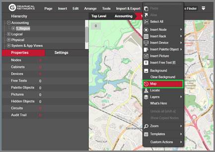
Map Specifications
Proceed to enter the extremal values for the map chosen as the background image. For that, you may want to use some reference points of your map and compare them to the same points on some other mapping engine (like Google maps) and write down the corresponding latitude and longitude values.
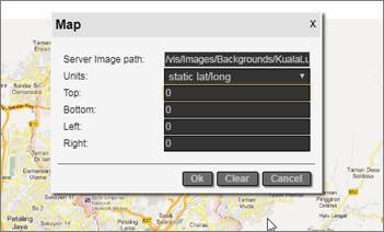
Embedding the coordinates
Once the coordinates have been embedded in the diagram, it the user hovers the mouse over the diagram, an indicator on the bottom left corner of the diagram area will show the current position of the mouse cursor in the assigned coordinate system.
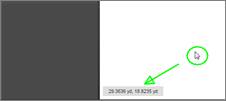
Diagram Coordinate indicator
This feature of embedding coordinates is only recommended when you need very simple mapping features and you don’t have the netTerrain OSP module. For real outside plant functionality, we recommend using our OSP module, which includes support for real dynamic mapping and number of improved rendering features better suited for outside plant documentation.
5.7.1.1 Measurements with embedded coordinates
Once coordinates have been embedded on a diagram, users can measure the distance between two nodes or measure the length of a link.
To measure the distance between two nodes, do the following:
1) Select the two nodes
2) Right-click on one of them and select the menu ‘Measure’ (or use the Measure button in the Maps menu)
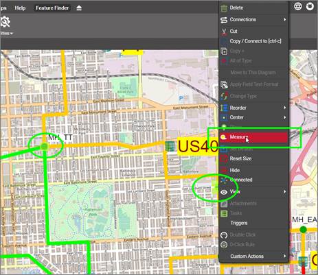
3) This will bring a pop up dialog showing the distance (as the crow flies)
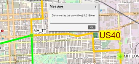
To measure the length of a link, do the following:
1) Right-click on one of them and select the menu ‘Measure’ (or use the Measure button in the Maps menu)
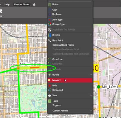
2) The pop-up dialog will now show the length, as well as the distance to the origin and destination
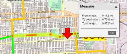
For link measurements, the distance to the origin and destination are taken from the exact point the mouse-click happened.
Link measurements also consider the bend points! This is especially useful for outside plant purposes when measuring total lengths of (straight) links with several bend points.
Attention!
When measuring lengths of links with bend points, the actual position of the bend point is what matters. For straight links this provides an exact measurement, but for curved links the actual path of the link will not coincide with the measured number since the bend points in Bezier curves lie outside of the line.
5.7.1.2 Using static latitude and longitude in maps
Latitude and longitude coordinates come in two flavors: static and dynamic. Static lat / long coordinates refer to coordinates set manually by the user. Dynamic coordinates make use of georeferenced maps (we devote a separate chapter for this feature). When using static latitude and longitude coordinates, netTerrain automatically computes cities that lie within the latitude/longitude coordinate boundaries. This can be used to place nodes automatically on a specific city and to find the nearest city to a specific point.
To place a node on a city, do the following:
1) Right-click on the node and select ‘Place’
2) A pop-up window with a list of cities will appear. Select the desired city and the node will move to the correct latitude / longitude position
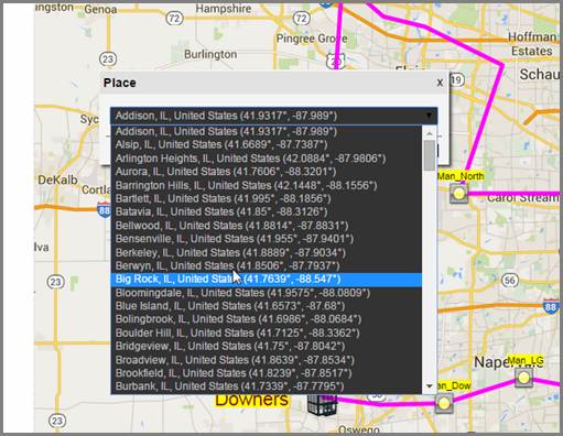
Automatically placing nodes on a city
The list of cities is pulled from a large table (in the netTerrain database), that contains over 100,000 cities worldwide.
Users can also right-click anywhere on the map and find the nearest city to the point where the click occurred by selecting the option ‘What’s here’. A pop-up window will appear showing the closest city to the corresponding latitude and longitude of the point that was clicked.
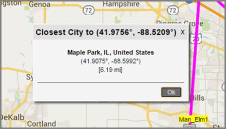
What’s here feature
5.8 IP toolset
The IP toolset is a little utility that lets users run useful commands or programs, such as ping, telnet or remote desktop, directly from the browser.
These programs work when the following conditions are met:
- The IP toolset has been enabled by an administrator (see admin guide)
- One or more commands or programs have been configured by the administrator (see admin guide)
- The IP toolset application has been installed on that machine
- The programs a user wants to run exist on that user’s client machine (the activation is client based because browser cannot allow the execution of client programs on their own for obvious security reasons).
Any clients that need to utilize this feature must run the IP toolset installer on their machine. To get the toolset installer, the user can download it from the Tools->Utilities menu:
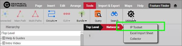
Downloading the IP toolset
The IP toolset feature manifests itself as a little drop-down arrow that pops up next to a property or displayed field that is formatted as IP addresses. The image below shows the execution of the ping command directly by clicking on the drop down arrow next to the IP address.
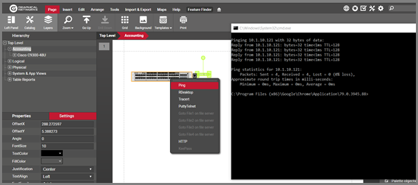
IP Toolset execution example
5.9 Triggers
netTerrain lets you create triggers, which are programmable actions that can be launched when an event occurs. This is done through the netTerrain SOAP API and the so-called event-handler. Currently the event-handler supports one event only, which is the on-property change event.
The netTerrain Programming guide explains how to create custom modules, which is outside the scope of this guide, so here we will just focus on how to use an existing custom module for a trigger.
Since triggers apply to property change events for an object like a node, link or text, first you need to right-click on that object and click on 'triggers'.
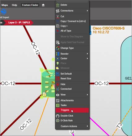
This will open a dialog that looks a bit like the dialog used for attachments or tasks. Next do the following:
- Click on the 'Add new' button
- Choose the object property for which the trigger needs to run
- Pick the dll module that will be executed upon the property value changing
- Pick the module method, essentially the function that will run upon the property changing
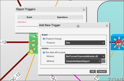
Trigger dialog
It is important to understand that on-property change event triggers do not behave like a visual override. For the trigger method to run, the selected property for the object simply needs to record any change in value, not a specific value which is what visual overrides expect.
Triggers also work with links and text objects.
6 DCIM objects
In previous chapters we learned how to work with nodes and links in netTerrain. A node is a very unassuming yet flexible object in netTerrain: it can represent anything from a building to transportation equipment, a data center object, location or even a chair or person. Nodes can, of course, relate to each other or to a smart object. Yet nodes are rather modest compared to their cousins, the DCIM objects (or “smart” as we sometimes like to call them). Nodes, as opposed to smart objects are not aware of subcomponents they may contain, its physical dimensions, let alone more sophisticated properties like weight or power usage.
This guide will show the process of adding one device or rack at a time. If you have a very large list of devices and racks that need to be added (100+), you may want to consider using the Integration Toolkit (ITK) to automate and speed up the data entry process.
6.1 Regular nodes vs. ‘Smart objects’
If you are a user of netTerrain DCIM you probably want to use smart objects in case you need to document entities like routers, switches, cards or cabinets, so that you can take advantage of some of the business rules and automation that netTerrain offers. These business rules and features include:
For devices and cards:
-
An extensive predefined library of makes and models
-
Automatic creation of subcomponents (ports and slot)
-
Automatic creation of a background image
-
Awareness of physical size and weight
-
Easy “snap in” for rack mounting
-
Awareness of power consumption
-
Ability to receive automatic alarms from the Integration Toolkit (ITK)
-
More comprehensive modeling capabilities such as the ability to specify reference node location
-
Ability to restrict which card types can be positioned under which slot
-
Pre-defined reports in the dashboard
For racks:
-
Rack unit count and awareness of rack unit occupancy
-
Automatic creation of a background image
-
Smart aggregation of dependent devices for rack occupancy, power and weight consumption
-
Pre-defined visual overrides on floor plans for rack occupancy, power and weight thresholds
-
Pre-defined reports in the dashboard
Generic nodes (or simply nodes) have none of these capabilities. They are simply modeled as objects that have an image, a set of fields, and visual overrides.
6.1.1 Can I use nodes to represent devices or racks?
None of the features for smart devices described above prevents a user from utilizing generic nodes to represent devices. In those cases, netTerrain really doesn’t see a difference between your “nodes as devices” and any other node. You can certainly add a node that looks like a router and later connect it to another instance of a generic node that looks like a switch. The caveat is that netTerrain will treat these objects as any other generic node. What this means, is that if you want to document the ports of a router or switch, you will need to create them manually, and if you want to rack mount it, you will have to resize it and fit it inside a rack diagram manually.
If you have a license of netTerrain Logical, generic nodes must be used in place of smart devices, since this product does not have smart devices as a feature. Otherwise, we only recommend using generic nodes in place of smart devices if you have little use for tracking things like physical rack locations, devices subcomponents, port occupancy, power and weight consumption, among other features.
The creation and maintenance of devices, racks and other so-called smart objects in netTerrain is only available with a netTerrain DCIM license. In this chapter we will be working with racks and devices, then subsequently the assignment of cards to devices and devices to racks. The section also covers ports and their connectivity.
6.1.2 The netTerrain hardware model hierarchy
The modeling of racks, devices and cards is covered in the Power User guide, but from the standpoint of an end user in netTerrain it is important to know how the netTerrain hardware model works.
netTerrain provides a very flexible, n-layered, object-oriented hardware model, where the users have complete control over what a rack, a device and a card constitute. We already know that each object type can have unlimited properties and behaviors, but from a hardware model point of view, netTerrain supports the following hierarchy:
-
Rack or Node (User-defined: region, site, room, bazinga object, Planet Mu...)
-
Node
-
Device
-
Node
-
...ad infinitum
-
Port/s
-
Card/s
-
Node
-
...ad infinitum
-
Port/s
-
Daughtercards
-
Node
-
... ad infinitum
-
Port/s
-
Daughtercard/s
-
... ad infinitum
As we can see, this hierarchical model allows for any possible hardware scenario, real-world or imagined. Even the definition of a rack is very broad: it doesn’t really have to be an actual rack.
6.2 Racks
Racks are containers of other objects, specifically devices that allow a rack mounting process. For rack mounting, racks require a certain width (specified in inches) and a certain height (specified in inches as well). In addition, racks have a certain number of rack units (typically one rack unit equals 1.75 inches). All these properties are defined during the rack modeling process and are reviewed in the Power User Guide. Finally, racks may also have a certain power availability and weight capacity.
We assume that before adding a rack or device, you already have some sort of hierarchy in place. This is not strictly needed, as you can place smart objects anywhere in the netTerrain hierarchy, but it usually makes sense to have higher level objects representing sites, buildings, floors or rooms, which provide context for the device locations.
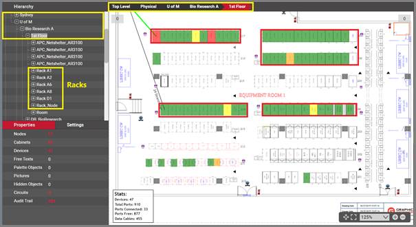
Typical Data Center hierarchy with a room section view and racks
Also, prior to adding devices to netTerrain make sure you already have the appropriate rack types modeled in the catalog. If a rack type you are trying to add is not available from the rack menu button, it will have to be modeled in the catalog. These tasks are covered in the Power User Guide.
6.2.1 Adding a new rack to the project
Racks are added in netTerrain through the rack button in the insert menu, the diagram right-click context menu or through a simple drag and drop process from the catalog.
6.2.1.1 Method 1: using the rack menu option
The traditional way of adding a rack is from the insert menu. Just click on the rack button and several options become available. You can add a generic rack (this is the green rack at the top of the menu) and then change its type to something else, or simply click on one of the racks below, or categories (if there are any) and find the rack type you need.
If the rack type you are looking for is not on the drop-down list, it may have to be modeled in the catalog or it just isn’t part of the favorites list. In the latter case, the catalog administrator simply needs to make sure that rack type is checked as a favorite (see Power User Guide).
The categories and nodes you see here by no means represent the entire catalog. They are just the categories and node types defined as favorites. By default, netTerrain does not ship with rack categories as typically, you will only have a handful of different rack types in your data center. If you do have categories, these are, of course, all user-defined and can be modified at will by a power user. They contain the racks associated with that category that were also marked as favorite in the catalog.
Once you identified the rack type you need, you click on it and it will be added to the top left corner of your diagram. You just created what we call an instance of that rack type.
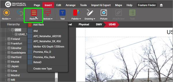
Rack menu button
Each instance of a rack type will reflect the custom properties that were defined in the catalog for that type. In other words, all instances of a certain rack type share the same specific set of properties.
When you click on that instance, the properties will be displayed on the properties window on your left. Any user with updater permissions or better can modify the values for any of the custom properties.
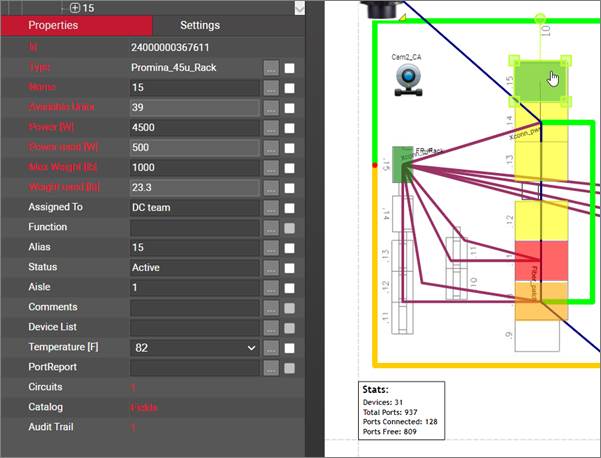
Properties for the rack. All racks of this type share the same properties
You can change the type of a rack later but consider that if you change the type after devices were rack mounted on the rack, they will be unmounted if the new type differs in dimensions.
Attention!
When you change the type of a rack, all the properties will change as well. Any data that was filled out for the old rack type will be lost, since those properties may not apply anymore.
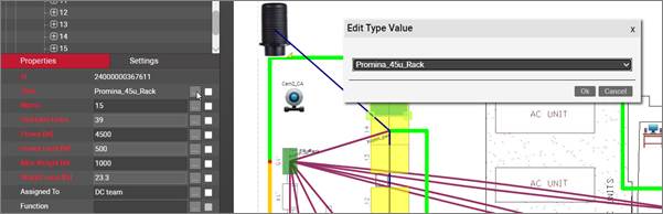
Changing the type for a rack
6.2.1.2 Method 2: using the right-click diagram context menu
As an alternative method for adding racks you can do the following:
3) Open the diagram context menu by right-clicking anywhere on the diagram
4) Click on Insert Rack -> desired category or rack
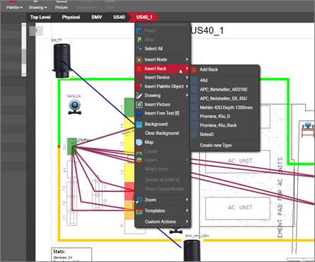
Inserting a rack using right-click context menus
The newly inserted rack will be placed on the spot where the right-click action occurred.
6.2.1.3 Method 3: dragging and dropping from the catalog
The easiest way to add devices in netTerrain is to just drag and drop them from the catalog. To do that, the catalog needs to be displayed (see above). If it is not displayed, just press ‘F3’.
Once the catalog is visible, you can use any of the tools you want to find the desired object (see catalog structure section):
-
‘Dia’ and ‘Fav’ checkboxes
-
category drop down box
-
catalog search
Once you find your rack, just drag and drop it on the diagram. That’s it!
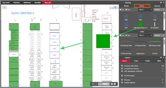
Dragging and dropping a rack onto a diagram
6.2.1.4 Method 4: dragging and dropping an image from a browser or folder
Just as you do with nodes, there is a nice trick to add a rack into the project quickly: by dragging and dropping an image from a folder or browser.
The best way to use this trick is to have both the netTerrain browser and the folder or website with the image side-by-side. Then, just drag and drop the desired image to the netTerrain diagram, as shown below:

Create a picture by dragging and dropping an image
After you dropped the image on the diagram, netTerrain gives you the option to create it as a floating image (picture), a node type, a device type, or a rack type. Choose the ‘rack' option:
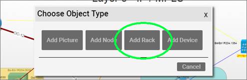
Choosing the 'Rack' option to create a new rack
This process creates a rack type in the catalog using that image. The type is called something like 'Rack #1' and has no custom properties. You can later on (as a power user) edit the rack type properties, model it, change the type name, add new custom fields and overrides and much more. The nice thing about this trick is that it gets you started quickly.
Tip:
You can also perform the same operation by simply copying a picture from your computer with ctrl-c and then pasting it on the netTerrain diagram.
6.2.2 Working with racks on a floor plan
Once your rack is on the floorplan you can also resize the rack icon and place it correctly on top of the floor plan view or room section (if applicable).
When a rack is created, two images are associated with it. The rack icon represents the top view of the rack on the floor plan or room section and is typically a square (as depicted in the image below).
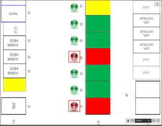
Rack icons on a room section
The second image used for racks is the rack front and/or back image, representing the rack mountable area, accessible by double-clicking on the rack icon.
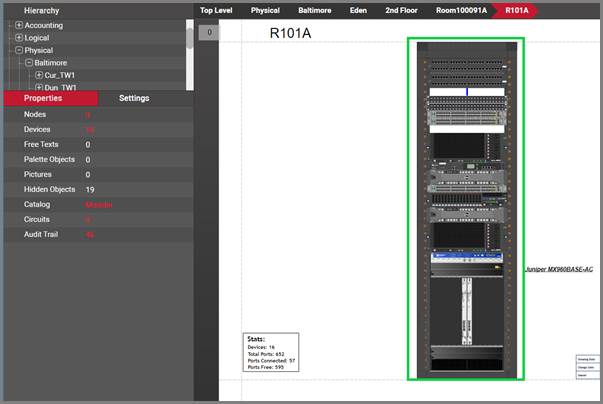
Rack front image with rack mounted devices
The rack front and back images are background images that cannot be resized or moved on the diagram, as they represent the rack mountable area. If the rack mountable area needs to be changed, this is done in the rack modeler (see Power user Guide).
6.2.3 Rack aggregate properties and visual overrides
As you start rack mounting devices inside a rack, the rack (being a smart object) aggregates relevant data and stores it as part of its properties. These aggregate values are used in conjunction with editable environmental properties that inherit a default value from the type. While the latter can be edited on a per instance basis, the aggregated values cannot be edited, as they are calculated. These special rack properties are the following:
-
Available Units (aggregated): this is the number of rack units that are still available for the rack
-
Power [W] (inherited from type – editable): this is the predefined static power value assigned in the rack modeler. The existence of this property does not prevent you from creating other power figures as custom properties.
-
Power Used [W] (aggregated): this is the sum of all nameplate power figures for devices rack mounted on that rack. These device nameplate power figures are also created during the device modeling process and are static numbers. netTerrain can also aggregate other power figures into custom fields. For example, dynamic power values could be discovered and automatically populated into a device custom field, and later aggregated as an expression in a rack custom field.
-
Max Weight [lb.] (inherited from type – editable): this is the predefined static weight capacity value assigned in the rack modeler. The existence of this property does not prevent you from creating other custom properties related with weight.
-
Weight Used [lb.] (aggregated): the sum of the device weight rack mounted on that rack. The device weight values are also created during the device modeling process.
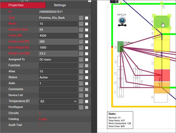
Rack special fields (in red)
Because of aggregate properties being automatically computed for racks, netTerrain can dynamically change the colors of racks based on three core properties: rack unit occupancy, used power and weight. These visual overrides can be overridden with custom overrides as well, but the main difference between these predefined overrides and custom ones is that the former overrides are included as radio buttons in a Rack Override feature that allow users to switch from one override criteria to another, as depicted below.
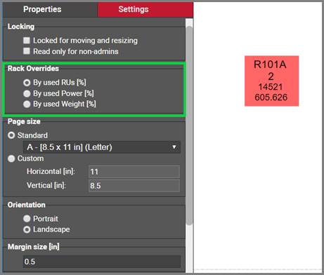
Predefined rack overrides
With this feature, a user can switch from one override criteria to another, and the rack colors will change accordingly. These predefined overrides to have a fixed range of colors based on the following rules:
- 0 to 25% is represented in green
- 25% to 50% is represented in yellow
- 50% to 75% is represented in orange
- 75% and higher is represented in red
6.2.4 Working with dual racks
The netTerrain catalog supports rack views with multiple containers, which lends itself to using front and back views. For that to work, the rack itself must be modeled as a dual rack, which is covered in the Power User guide.
To rack mount devices on dual racks, make sure you are indeed using a rack properly modeled as dual.
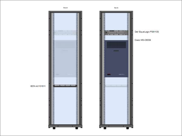
A dual rack view with CFBM
With CFBM when you rack mount a device on the front, netTerrain will show a faint image of the device on the back and vice versa. That way, users already see from a graphical standpoint that those units are unavailable on either side of the rack. The image above shows a dual rack with CFBM enabled, with two devices mounted on the front and a patch panel on the back.
Also, it is interesting to note that if you try to mount a device overlapping with any of the “faint” icons, the device will not snap inside the rack. This is expected since the rack units are already taken.
6.2.5 Rack composite views (multiple racks in one view)
In many cases users want to see multiple racks side by side, showing all the rack mounted devices in one view. This is possible using the rack composite view feature. These are some of the capabilities of the feature:
- You can combine up to 8 racks in one view
- You can pick any set of racks (between 2 and 8) from a given floorplan, they don’t need to be contiguous
- The created view is a dynamic view, meaning that the diagram is only in memory and will not be permanently stored
- Composite views let you create cables between devices on different racks, all from one diagram.
To launch this feature, do the following:
- First select the racks from the floorplan
- Right click (or alt-c) and click on 'composite'
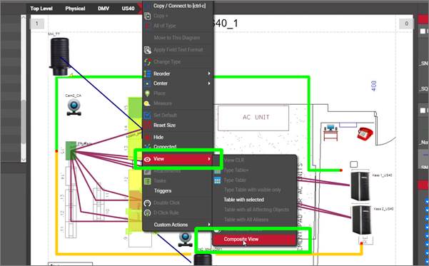
Launching the rack composite view
Once the composite view is launched, netTerrain will create a dynamic view of all the selected racks, rendered side by side stretching the whole page.
The names of all the racks are displayed on the header, separated by commas and each rack will have its name on top of the container. Notice that the racks may loo a bit different in this view than in the normal view, since we only display the rackmountable area (container).
From this view you can create cables between devices using the multicable feature: select two devices and hit [alt-m].
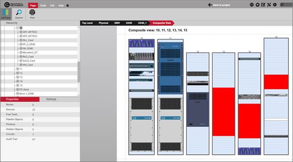
Rack composite view
6.3 Devices
If you are a user of netTerrain DCIM you probably want to use smart objects in case you need to document entities like routers, switches, cards or cabinets, so that you can take advantage of some of the business rules and automation that netTerrain offers. These business rules and features include:
-
An extensive predefined library of makes and models
-
automatic creation of subcomponents (ports and slot)
-
automatic creation of a background image
-
awareness of physical size and weight
-
easy “snap in” for rack mounting
-
awareness of power consumption
-
ability to receive automatic alarms from the ITK
-
more comprehensive modeling capabilities such as the ability to specify reference node location
-
ability to restrict which card types can be positioned under which slot
-
pre-defined reports in the dashboard
Strictly speaking, a device is an instance of a type that was created in the catalog using the category ‘Device’ during the creation process. Of course, this definition is recursive, but it is really up to the user to define what exactly constitutes a device. Because of the flexible nature of netTerrain, you could in theory model anything as a device, but in general it is any box (router, server, UPS, switch, patch panel, etc.) that contains subcomponents (such as ports and slots) and has certain default physical and environmental parameters such as size, power and weight.
During the modeling process, devices are built or “modeled” with specific properties, for instance rack unit size, power and weight capacities. In addition, subcomponents such as ports and slots can be added to a device. As mentioned before, this provides a high degree of automation, since every time an instance of a specific device type is added in the project, all the type properties are inherited, and all the subcomponents are automatically created.
A default installation of netTerrain DCIM contains a few thousand common types, but as you will learn later, adding new ones is not complicated. Moreover, if your netTerrain maintenance contract is current, you can request new models from us at no extra charge.
6.3.1 Adding a new device to the project
There are several ways of adding a device to your project, including bulk, database, network discovery and API imports. However, in this guide we only review manual data entry techniques. You can review the import/export, ITK and programming guides to explore other methods.
6.3.1.1 Method 1: using the device button in the menu
The traditional way of adding a device is from the insert menu. Just click on the device menu button and several options become available. You can add a generic device (this is the blue node on top of the menu) and then change its type to something else, or simply click on one of the categories and find the device type you need. The categories and devices you see here by no means represent the entire catalog. They are just the categories and device types defined as favorites. Categories you see in this menu are user defined, can be modified at will by a power user and they contain the devices associated with that category that were also marked as favorite in the catalog.
Once you identified the device type you need, you click on it and it will be added to the top left corner of your diagram. You just created what we call an instance of that device type.
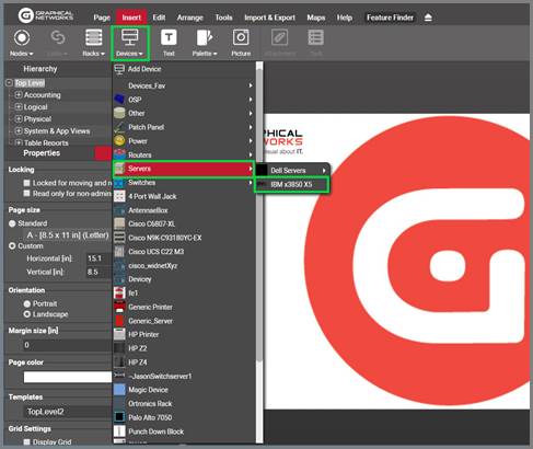
Device menu button
Each instance of a device type will reflect the custom properties that were defined in the catalog for that type. In other words, all instances of a certain type share the same specific set of properties.
When you click on that instance, the properties will be displayed on the properties window on your left. Any user with updater permissions or better can modify the values for any of the custom properties.
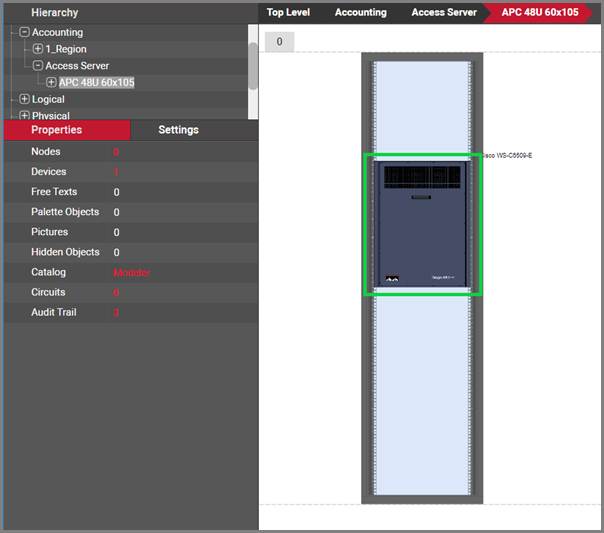
Properties for the router device. All routers of this type share the same properties
If a generic device is added, a user can later change to some other type, by selecting it from the type menu, as shown below.
Attention!
When you change the type of a device, all the properties will change as well. Any data that was filled out for the old device type will be lost, since those properties may not apply anymore.
More importantly though, when you change a device type, its subcomponents like ports and slots change. This triggers a series of events discussed below.
6.3.1.2 Method 2: using the right-click diagram context menu
As an alternative method for adding devices you can do the following:
5) Right-click anywhere on the diagram to open the diagram context menu
6) Click on Insert Device -> desired category or device
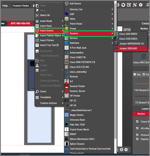
Inserting a device using right-click context menus
The newly inserted device will be placed on the spot where the right-click action occurred.
6.3.1.3 Method 3: dragging and dropping from the catalog
The easiest way to add devices in netTerrain is to just drag and drop them from the catalog panes. In order to do that, the catalog needs to be displayed (see above). If it is not displayed, just press ‘F3’.
Once the catalog is visible, you can use any of the tools you want to find the desired device:
-
‘Dia’ and ‘Fav’ checkboxes
-
category drop down box
-
catalog search
Once you find your device, just drag and drop it on the diagram. That’s it!
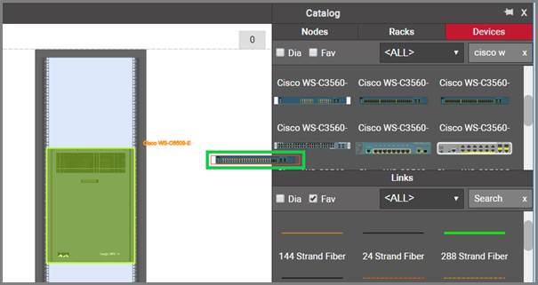
Dragging and dropping a router onto a diagram
6.3.1.4 Method 4: dragging and dropping an image from a browser or folder
Just as you do with nodes, there is a nice trick to add a device into the project quickly: by dragging and dropping an image from a folder or browser.
The best way to use this trick is to have both the netTerrain browser and the folder or website with the image side-by-side. Then, just drag and drop the desired image to the netTerrain diagram, as shown below:

Create a picture by dragging and dropping an image
After you dropped the image on the diagram, netTerrain gives you the option to create it as a floating image (picture), a node type, a device type, or a rack type. Choose the ‘device' option:
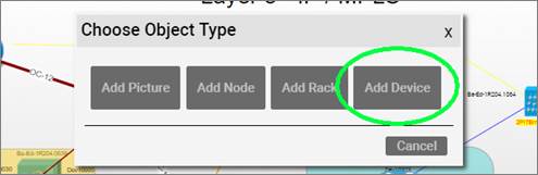
Choosing the 'Device' option to create a new rack
This process creates a device type in the catalog using that image. The type is called something like 'Device #1' and has no custom properties. You can later on (as a power user) edit the device type properties, model it, change the type name, add new custom fields and overrides and much more. The nice thing about this trick is that it gets you started quickly.
Tip:
You can also perform the same operation by simply copying a picture from your computer with ctrl-c and then pasting it on the netTerrain diagram.
6.3.2 Working with devices
Devices inherit a series of properties defined in the catalog:
-
device icon
-
a backplane image
-
subcomponents (if applicable)
-
predefined properties
To access the backplane of the device and its subcomponents, simply double-click on it.
When a device is created, two images are associated with it. The device icon represents the front view of the device and is typically a vendor specific picture.
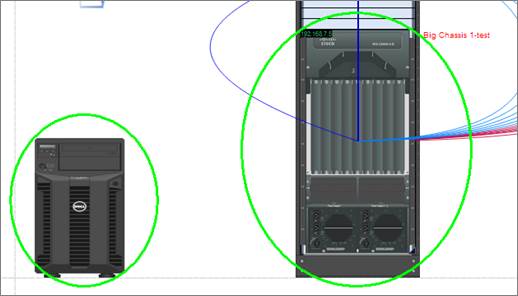
Device icons in a rack diagram
The second image used for devices is the backplane image, representing the back of the device where ports, slots and cards reside, accessible by double-clicking on the device icon. This image, along with the subcomponents is also referred as the subcomponent view.
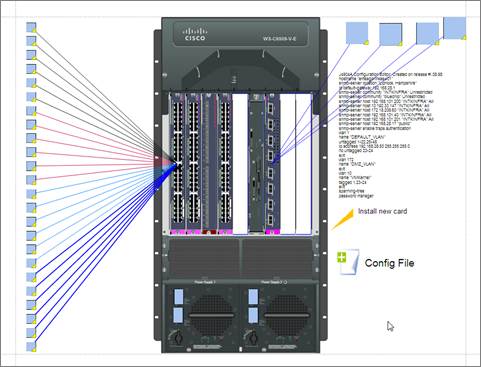
Device subcomponent view with the backplane image
The device backplane image cannot be resized or moved on the diagram, as it represents the physical view of where ports, slots and cards are placed. If that image needs to be changed, this is done in the device modeler (see Power user Guide).
Tip:
If you need to show the front and the back view of a device in the device subcomponent view simply use a composite image in your catalog.
6.3.2.1 Changing the type of a device
To change the type of device (make and model) of an existing instance, select the device and change the type from the properties window.
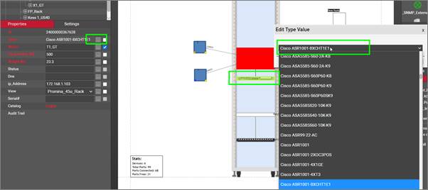
Changing a device type using the drop down list of device types.
When a device type is changed and has connections you will be presented with a message asking to verify the change (since it may affect several connections).
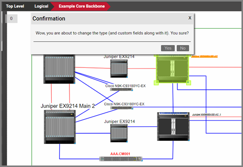
Changing a device type
As the make and model changes, so do the underlying slots, and ports. netTerrain does provides some logic to try to preserve the connections, using port names as a reference. If no matching port names exist for a given connection you will be notified of the number connections to be dropped.
Also, as mentioned before, if the data fields are different between the old device type and new device type then those property values will be removed as well.
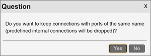
Connection preservation dialog box
If you decide to keep the existing connection(s) then you will see a message box describing how many connections will be preserved.
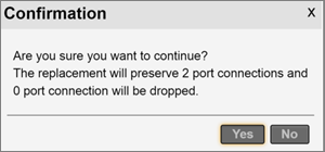
Connection preservation details
6.3.2.2 Predefined device properties
Devices have two predefined properties that are inherited from the catalog:
-
Peak Power [W]: this is the predefined nameplate power assigned in the device modeler.
-
Weight [lb]: this is the predefined static weight capacity assigned in the device modeler.
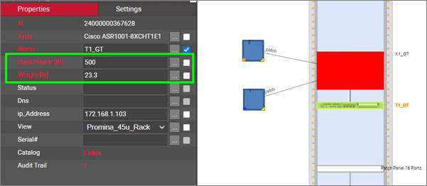
Predefined device fields
As opposed to aggregate functions for racks, these properties can be overridden on an instance by instance basis. Also, users can create additional custom fields representing power readings, which can in turn be the result of a discovery or some other importing mechanism.
6.3.2.3 Mounting a device on a rack
To mount a device on a rack, drag it to the rack mountable area. You will notice that netTerrain tries to snap the device on the nearest rack unit (provided there is enough space to fit the device).
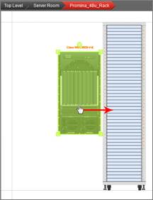
Rack mounting a device
Once a device is rack mounted, netTerrain flags those units as occupied and aggregates them for proper rack visual override processing.
6.3.2.4 Rack mounting using increments of 1/3 of a rack unit
Racks usually allow mounting in increments of 1/3 of rack units. To do that, simply select the device and move it up or down using the arrow keys on your keyboard instead of the mouse.
6.4 Device subcomponents: slots, cards and ports
Devices can have three types of subcomponents, which can be viewed by double-clicking on the device icon:
- Slots
- Cards
- Ports
Devices can, of course, contain other nodes which can have anything underneath. Ports can also appear underneath a card or a daughter card, as we saw in the netTerrain hardware model at the beginning of the chapter.
6.4.1 Slots and Cards
Slots are placeholders for cards and they are defined in the catalog, typically on top of the device backplane image. Devices that contain slots are sometimes referred to as modular. Slots cannot be moved or resized for an instance (it wouldn’t make much sense to do so, when was the last time you could stretch a card on a router!). Slots that have been mapped to card types in the catalog can be populated with cards. The card types that are available will depend on the catalog setup (see Power User guide).
To assign a card to a slot first make sure you go to the device backplane, which is where you find the slots. Notice that now the catalog includes a cards tab. Click on it, and all the cards that have been mapped to the current device type will be populated inside the tab.
Now just drag and drop the desired card type to the slot you want to populate and that’s it!
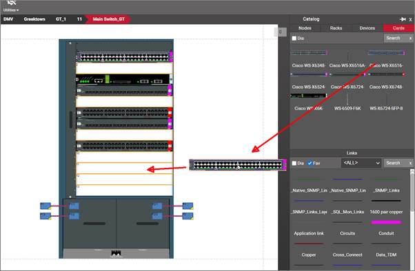
Populating a slot with a card
To remove a card from a device, you basically just turn it back into a slot, as shown in the image below, using the type <Empty Slot>:
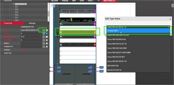
Turning a card back into an empty slot
Another way to remove the card from the slot is to simply select it, and then press the ‘del’ key. How easy is that?!
A card is modeled in the catalog pretty much like a device (see power User guide). A card can contain:
- Ports
- A background image
- Other cards (or daughtercards)
- Other nodes
Once a card has been created, its ports are also created automatically, just like with a device. To see the ports and other subcomponents inside a card just double-click on it.
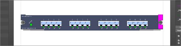
Card backplane with automatically created ports
6.4.1.1 Predefined card properties
Cards, just like devices, have the same two predefined properties that are inherited from the catalog:
-
Peak Power [W]: this is the predefined nameplate power assigned in the card modeler.
-
Weight [lb]: this is the predefined static weight capacity assigned in the card modeler.
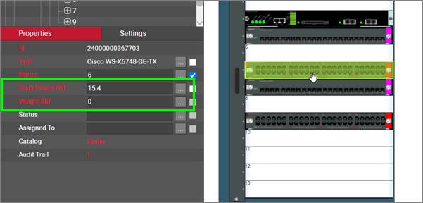
Predefined card fields
These properties can be overridden on an instance by instance basis. Also, users can create additional custom fields representing power readings, which can in turn be the result of a discovery or some other importing mechanism.
6.4.1.2 Changing slot positions for a card
Sometimes you need to change the slot position on a card, without losing any connections on it. To do that simply cut and paste the card: select the card and press ctrl-x and then select the destination slot and press ctrl-v (notice how we are not bothering to provide the right-click context options anymore, you are becoming the shortcut guru!).
6.4.2 Ports
Ah, the famous ports!
Ports are... well, we know what they are, but from a netTerrain perspective, ports are subcomponents of devices or cards and they are the last link in the hardware hierarchy since you cannot drill down further down.
As opposed to devices and cards, ports do not have different types. All ports share the same set of properties and the only thing that can differentiate one from another is some value in some field.
6.4.2.1 Port fields
Besides the name itself, ports have the following predefined fields:
- Protocol: this would typically be the layer 1 standard, which is a user defined list (such as Ethernet, RS-232, etc.)
- Connector: the physical connector, which is a user-defined list (RJ45, SC, Power, etc.)
- Status: user-defined list of values (up, down, etc.)
- Slot Name: calculated field which simply reflects the slot position of the containing card. If the port is directly in a device backplane this value is empty
None of the fields are mandatory (Slot Name is not even editable as it is calculated).
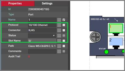
Port fields
6.4.2.2 Reference ports
Just as with other objects, any inter diagram link that connects to a port will display the reference port on the other end.
The netTerrain device / card modelers let the power user predefine the position of reference ports on the device and card backplane. This saves the users a lot of time in moving reference ports around to make the diagram look tidy. The image below shows a patch panel that is fully connected where all the reference ports were nicely aligned automatically by virtue of their positions being predefined for that patch panel type in the modeler.
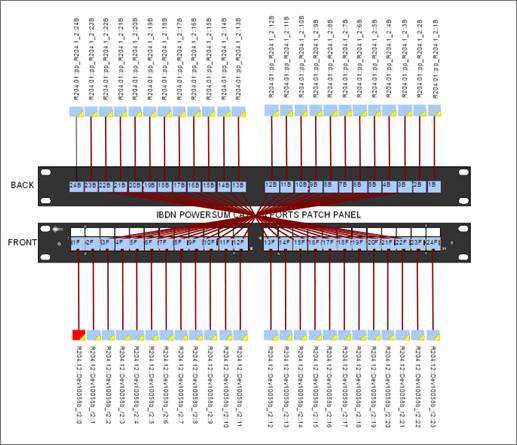
A patch panel with properly arranged reference ports
Also notice the displayed fields for the reference ports: they show a full ancestry path specifying the location of the port on the other end of each local port. This can also be automated using an expression in netTerrain that captured the location data for each reference port.
By setting the expression as a default for any custom field, and making that field displayed, every time a connection is made, the full path displayed field shows up automatically. In the example above, we used the expression $zz_Port_RackDevicePortPath([id]), which is a predefined expression that ships with netTerrain.
6.4.2.3 Port overrides
Just as with any other node type, ports allow overrides simply by setting up a rule for any of its fields. Port overrides are set up by the Power User in the catalog (see Power User guide).
The image below shows a port with overrides based on a field called ifOperStatus.
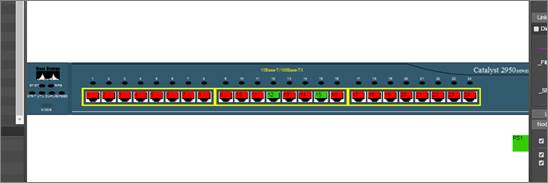
Port overrides based on operational status
7 Bulk imports and exports
As mentioned earlier in the guide when reviewing the menus, netTerrain includes a number of bulk import and export features, including:
- netViz import
- Microsoft Visio import and export
- Excel import
- KML / KMZ import & export
- PowerPoint export
- PDF export
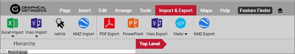
Bulk import and export buttons
For the netViz and Visio imports to work correctly, Visio and netViz need to be installed on the netTerrain application server and properly configured (see Import / Export Guide). KML / KMZ imports will be reviewed in the Outside plant chapter.
7.1 Importing netViz projects into netTerrain
Once the netViz importer is set up, end users can import netViz projects into netTerrain.
Consider that netTerrain and netViz differ in many ways, which means that for an optimal import process to work, it is recommended that you first prepare the netViz project and catalog for proper importing.
7.1.1 Preparing the netViz file for the import process
As mentioned above, because of differences in functionality and business rules it is recommended to properly set up a netViz project before the import process is launched. Follow the steps below to get the most out of your netViz migration.
1) Save and compact the netViz project. It is recommended that you use a different name for the project, so you always keep the original.
2) Remove print templates and composite views. We cannot import these due to netViz export limitations.
3) Check the project for unconnected links (in netViz tools/unconnected links). netTerrain does not allow dangling (unconnected) links. If you find some then they need to be linked or they will not be imported. Create a dummy connection point in the netViz catalog and use this if you need a connection point.
4) Delete any catalog types that are not used, unless you want to import the unused catalog objects. To do this in netViz, go to file/catalog/delete types. Then choose the option to delete all unused types. Do this for nodes and links.
5) Combine any nodes or links that have the same name or change the name of these nodes (if you do not change redundant names then some of the nodes and links will be dropped). You can use replace type if needed.
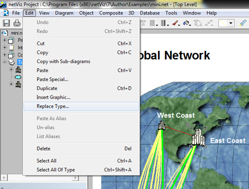
6) Perform a save and compact on the project.
7) F3 to edit the internal catalog. Check all node and link fields. All field names must be unique for each node or link type. Also, if any node or link field is called ‘name’, ‘id’ or ‘Type’ then it should be renamed since these are netTerrain reserved field names.
8) The field that has the name information (blue field in netViz) should be set to be the first field for a node or circuit within the netViz catalog before performing an import. This will ensure a proper name is displayed after import.
9) Proceed with the netViz import as described below.
7.1.2 Manual process for netViz imports
In some cases, when netTerrain cannot launch netViz automatically, a netViz project can be imported in manual fashion. Consider that the following steps require access to the netTerrain application server, in which case you may need to contact the system administrator.
If you have netViz properly set up on the application server, you may skip this section and import netViz projects simply by using the netViz import button.
1) Open the basic script called “NVEXPORTscript.bas” located in the C:\Program Files (x86)\Graphical Networks\netTerrain\Utilities folder with notepad and change the output folder path.
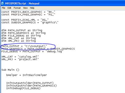
2) Create the output path folder in this instance (called C:\nvoutput).
3) Start netViz and open the project that will be converted.
4) Open the Basic Editor feature in netViz.
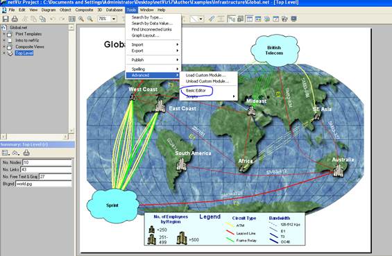
5) Load the “NVEXPORTscript.bas” module
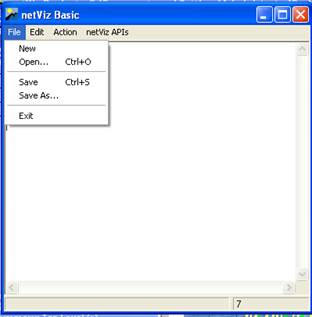
6) Press run
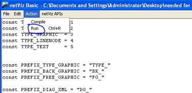
7) After the process is completed you should see the following message:
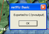
8) ZIP up the folder called “nvoutput” (the folder you created on the C drive).
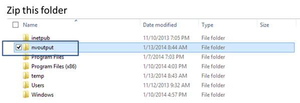
9) Log into the netTerrain server and then press the netViz import button.
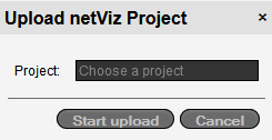
10) Proceed to upload the ZIP file.
Once you completed these steps, the import process will begin. This process usually imports a few objects per second, so for large projects the import may take several minutes or even hours.
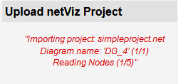
After the import is completed, a green generic node will be placed on the diagram where the import was launched. The node will have the name of the netViz project and the entire contents of the project will be placed underneath that node.
7.1.3 Importing netViz automatically
Log into netTerrain and press the “netViz import” button from the Import & Export menu. Upload a netViz project and wait for the project import to complete. Yeah, that’s it. The tricky part is to get IIS to work in concert with netViz access permissions, as described earlier in the chapter.
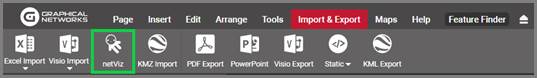
netViz import button
After the import is completed, a green generic node will be placed on the diagram where the import was launched. The node will have the name of the netViz project and the entire contents of the project will be placed underneath that node.
7.1.4 Importing several netViz projects in bulk
This task requires the help of a netTerrain system administrator and assumes the netViz importer is ready for automated imports and was properly set up on the server (see Import / Export guide).
When having to import numerous netViz projects, using the import button method may be inefficient and tedious. netTerrain allows for bulk imports of netViz projects but requires server file access to the webserver to upload netViz projects.
1) Ensure the following setting is present in the web.config file above </appSettings>
2) Add the netViz projects to the folder (or the custom installation folder):
3) From the netTerrain project click on <ctrl> + <alt> + <q> to access the netViz queue. Make sure the number of netViz projects matches the number of projects uploaded. Click ‘Import’ to begin the process.
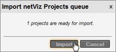
netViz import queue
7.1.5 Post import checkup
It is recommended to perform a basic sanity check in netTerrain to check that the netViz projects have been imported in a satisfactory manner.
Perform a catalog node and link comparison between the netViz catalog and the imported netTerrain catalog.
One way to do this is to print the catalog from netViz (files/summary/catalog/print). Use this printout to check off each field and verify all fields have been imported. Make sure all visual overrides are available and check the drop-down lists. Currently, drop down lists need to be recreated in netTerrain. If any fields are missing, it is usually because the fields in netViz are repeated.
As a second step, you can check the counters for both netViz and netTerrain. In netTerrain, the counter for nodes and links will be displayed in the diagram properties of the netViz import node sub diagram.
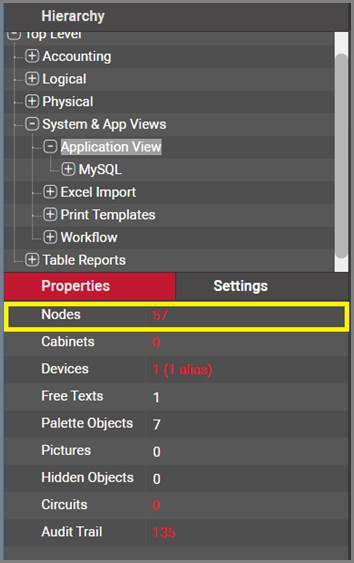
netTerrain node and link counters
The netViz counters can be obtained by opening the netViz project and then going to Project->Summary. Compare both counters and if they are close enough then the import was successful. It is not uncommon to miss some nodes and links. This is usually due to extra system nodes added in netTerrain and/or dangling links not being imported.
You can also:
Recreate any node and link field drop down lists that were not imported. Drop downs are not imported unless they are visual overrides in netViz.
1) Check visual overrides, to be sure they look correct.
2) Check link settings to be sure they have the appropriate color.
3) Check the nodes to see if any images need to be replaced.
4) Check background images for diagrams to see if any need to be replaced.
5) Clean up font sizes and positions for nodes and links. “Shape” object displayed fields should be set to the “center”.
7.2 Importing a Visio project
For Visio imports to work, the import process first needs to be set enabled and configured on the server (see Import / Export guide if you are an administrator). Once the Visio importer has been configured you can import a project from netTerrain directly.
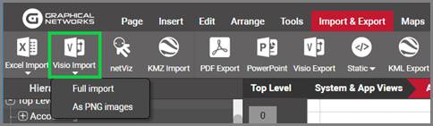
Visio import button
7.2.1 Static vs full project imports
There are two ways to import a Visio file: as a static searchable image or as a full project.
Static Visio imports simply convert the contents of each Visio sheet into a static image (no selectable nodes and links). As a bonus, all the attributes for each Visio object are indexed in netTerrain so that you can search for them. However, netTerrain will not pinpoint to the object that matches a search, since it is simply part of a static image, but at least it will take you to the image that contains it.
Full project imports are a lot more elaborate since they do convert the Visio objects into netTerrain nodes and links.
To start an import simply click the on the corresponding Visio import option and you should get a popup prompting you to upload a drawing.
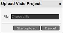
Uploading a Visio file
The drawings will be uploaded into the diagram you were in when you pressed the import button, under a top-level Visio icon that bears the name of the Visio project.
Because Visio drawings will not generate smart devices or racks in netTerrain (that concept does not exist in Visio), it is probably better to upload Visio diagrams onto a netTerrain diagram that holds (or will hold) logical data. Better yet, don’t use Visio; it’s not good for your health.
netTerrain currently only supports .vsd Visio file formats. If the file is larger than 10MB, then IIS may conspire on you and time out. Make sure you configure the settings in the web.config file to allow for large file uploads.
7.2.2 Using Visio stencils in the netTerrain catalog
Users can also import Visio stencils using the netTerrain web interface. After logging into the project, you should see a “Visio” icon under the Import & Export menu. Simply click the icon and you should get a popup to upload a stencil file in .vss format.
After the upload completes the stencils will be turned into netTerrain objects in the catalog “nodes” section. Any fields associated with the stencils will also be converted into netTerrain fields.
7.3 Exporting diagrams to Visio and PowerPoint
netTerrain gives users the ability to export diagrams to PowerPoint, for that presentation that you need along with your TPS report, as well as Visio, for the office masochist that also likes to reheat three day old salmon in the office microwave.
7.3.1 Server vs client-side exports
Visio and PowerPoint export rendering from the application server require those applications to be installed on the server. Often installing these applications on the application server is not possible. netTerrain provides an alternative export mechanism where the client renders the Visio or PowerPoint exports, instead of the server.
To enable server-side exports, the administrator can enable that setting from the admin console. However, when the server-side exports are disabled, users must download the export utility to take advantage of PowerPoint and Visio exports.
To download the Exporter tool, simply go to Tools->Utilities and click on ‘Exporter Tool’.
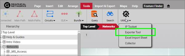
Exporter tool to export to Visio and PowerPoint client-side
To start the export process to PowerPoint or Visio click on one of the export buttons from the Import & Export menu.
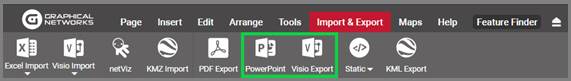
Visio and PowerPoint options
7.3.2 Visio export options
After clicking on the Visio export button, a dialog showing export options will be displayed, as shown below in the Visio export example:
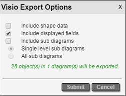
Visio export options
The following options are available when exporting Visio files:
- Include Shape Data: exported objects from diagrams will include all field data in the exported Visio diagrams.
- Include displayed fields, which means that any displayed data in the diagram will also be Visio export.
-
Include sub diagrams, which will export child diagrams to individual Visio sheets depending on the sub diagram options that are checked. These are:
-
Single level sub diagram, which exports the immediate level below
- All sub diagrams exports, which, well, you guessed it, exports everything
Note that the “all sub diagrams” option can take a very long time to process and is not recommended for large sets of diagrams. If your boss really must see the entire collection of diagrams then get ready for a really long coffee break (or better yet, give him access to netTerrain, it’s a much better app anyways).
If the file is rendered on the server the file will be made available for download by a server process.
7.3.3 PowerPoint export options
The PowerPoint export options are like Visio’s, except that no shape data option is present because PowerPoint does not support that feature.
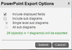
PowerPoint export dialog
The following are the options for ruining, I mean, exporting your lovely netTerrain diagrams to PowerPoint:
- Include displayed fields, which means that any displayed data in the diagram will also be displayed in the PowerPoint exported slides.
-
Include sub diagrams, which will export child diagrams to individual PowerPoint slides depending on the sub diagram options that are checked. These are:
- Single level sub diagram, which exports the immediate level below
- All sub diagrams exports, which sets you up for a long water cooler break
Also notice how netTerrain shows the number of nodes and diagrams to be exported. Just as with PDF, use this feature to determine if maybe a smaller portion needs to be exported.
7.3.4 Exporting and fetching the files
After clicking on ‘Submit’, the Visio or PowerPoint export process commences.
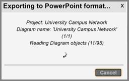
If the export is enabled on the client side, an .ntd extension file indicates that the process is ready for local rendering.

After you double click on the .ntd file extension netTerrain starts the rendering process.
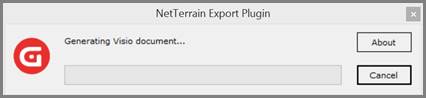
When the process is complete the file should automatically open.
7.4 Static exports: HTML and PNG
Sometimes you may need to create a static output for a netTerrain diagram that does not require any specific application to run. For that purpose, we introduced HTML and PNG exports as a mechanism to one or multi diagrams to a format that can be opened with a browser or an image viewer. An additional advantage of these methods is that it does not require any specific set up on the netTerrain server.
7.4.1 Exporting to static HTML
netTerrain diagrams are already in HTML5 format, so why this export option? Native netTerrain diagrams may be HTML, but you need to be connected to the netTerrain server to view them. Sometimes you may have a user that needs to look at a diagram without being connected to netTerrain. This is what this export feature is for.
To start the export process to HTML, click on the ‘Static’ button on the Import & Export toolbar and select the ‘Export as HTML package’ option.
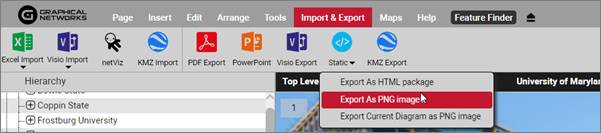
HTML package export
7.4.1.1 HTML export options
After clicking on the HTML export sub menu, a dialog showing export options will be displayed, as shown below:
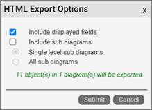
HTML export options
The following options are available when exporting to an HTML package:
- Include displayed fields, which means that any displayed data in the diagram will also be in the exported HTML diagrams.
-
Include sub diagrams, which will export child diagrams to individual HTML pages (hence the name HTML package) depending on the sub diagram options that are checked. These are:
- Single level sub diagram, which exports the immediate level below
- All sub diagrams exports, which, well, you guessed it, exports everything
Note that the “all sub diagrams” option can take a very long time to process and is not recommended for large sets of diagrams. If your boss really must see the entire collection of diagrams, then get ready for a long coffee break.
7.4.2 Exporting to PNG
To start the export process to PNG, click on the ‘Static’ button on the Import & Export toolbar and select one of the PNG export options.
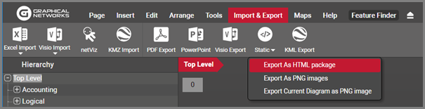
HTML package export
7.4.2.1 PNG export options
The first option of the highlighted sub menus above can export multiple diagrams in PNG format:
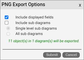
PNG package export options
The following options are available when exporting to a PNG package:
- Include displayed fields, which means that any displayed data in the diagram will also be in the exported PNG diagrams.
-
Include sub diagrams, which will export child diagrams to individual PNG files. These are:
- Single level sub diagram, which exports the immediate level below
- All sub diagrams exports, which, well, you guessed it, exports everything
The second option of the highlighted sub menus in the Static export button exports the current diagram only.
7.5 Importing data from Excel
This section covers the process and techniques required for importing devices, nodes and other objects into the netTerrain project using the Excel bulk import spreadsheet. The Excel bulk import can be used for inserting new objects as well as updating existing nodes (types and links can only be inserted).
7.5.1 Obtaining the Excel import sheet
The Excel import sheet can be downloaded directly from netTerrain if the administrator has enabled downloads from the netTerrain page.
Simply log into netTerrain, go to the Tools ribbon, and click on the Tools menu option. You can also go to the 'Import & Export' ribbon and click on the Excel Import button. If the Excel import sheet download has been enabled by the admin then you should be able to download the template excel import sheet directly.
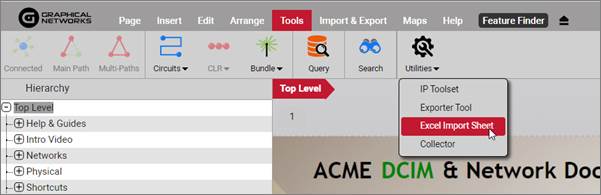
Excel import sheet download
If the administrator disabled the direct download of the Excel template, you must request from the administrator directly.
If you are the administrator, the spreadsheet can be found in the web installation directory of netTerrain. The default directory is: C:\ProgramData\Graphical Networks\netTerrain\vis. There should be a BulkImport.xls file in the base folder. This file must be used for the Excel import and should be copied and then modified. The file may be renamed.
Attention!
It is important that you maintain the existing format of the BulkImport.xls file and preserve its compatibility level; otherwise the Excel importer may not be able to process its contents.
7.5.2 Bulk import worksheets
The bulk import spreadsheet contains four worksheets:
- NodeTypes: creates new node types in the catalog
- LinkTypes: creates new link types in the catalog
- Nodes: creates new nodes or updates existing ones in the netTerrain project. Devices and cards are also allowed
- Links: creates new links in the netTerrain project
Attention!
You cannot generate catalog devices using the Excel spreadsheet. However, we support a large catalog of pre-modeled devices. If there are devices you would like to see modeled, please contact us at support@graphicalnetworks.com. As part of the maintenance we can model any types for you. Of course, our training and certifications also teach you how to do this in our device type modeler.
7.5.2.1 Node Types
To create new catalog node types, open the corresponding worksheet in the bulk import spreadsheet.
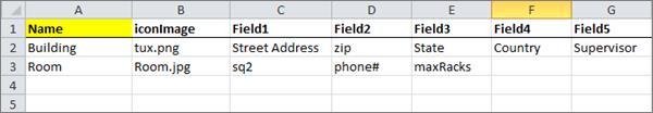
Node Types worksheet
The columns include:
- Name: This is the only mandatory field for creating a new Node Type and it represents the catalog node name
- iconImage: This field specifies the icon to be used when creating this node
- Field#: These are the property field names to be created for the node
Attention!
When specifying an icon image for the node type, you must zip together a ‘graphics’ folder, which contains the icon images, with the Excel spreadsheet.
7.5.2.2 Link Types
To create new catalog link types, open the respective worksheet.
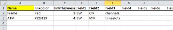
Link Types worksheet
The columns include:
- Name: Catalog link type name. This field is mandatory.
-
linkColor: mandatory field that specifies the display color of the link, which can be a hex color code or a color name (note that not all color names are supported)
-
linkThickness: mandatory field that specifies the width in pixels of the link
- Field#: These are the custom property field names to be created for the link
7.5.2.3 Nodes
This worksheet is used for creating and updating nodes and/or devices in the netTerrain project.
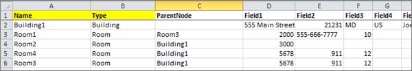
Nodes worksheet
The columns include:
-
Name: mandatory field that represents the name of the node
-
Type: mandatory field that identifies the type associated with the node. Once a type is defined, the custom fields in the spreadsheet will correspond to the custom fields associated with that node type in the netTerrain catalog
- ParentNode: the name of the parent node containing this node. If this field is blank, the new object will be placed on the ‘Top Level’ diagram.
- Field#: the custom fields associated with the type of the node. Each field in the spreadsheet has a sequential number prefix, which corresponds to the order of appearance of the custom field in the netTerrain catalog. For example, Field3 in the spreadsheet will populate the custom field that appears in order #3, for that type, in the netTerrain properties tab (not counting the id, name and type fields).
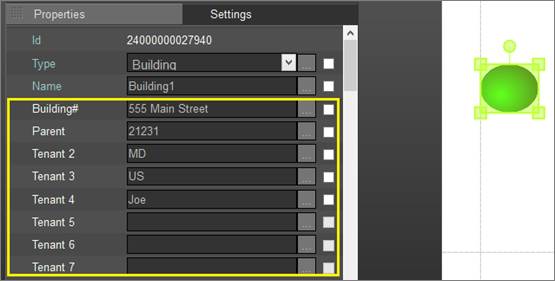
Making sense of the field numbering
Sometimes you need to place nodes under parent objects that do not have unique names. You can use composite keys in the excel import to concatenate an ancestry string, thus ensuring your nodes will be placed under the correct parent object.
Node delimiters for ancestry notation use the ‘>’ symbol. For example, if you want to place a node under Site ‘Baltimore’ and Rack ‘1’ then you would use this notation for the parent field:
7.5.2.4 Assigning cards to a device slots
Before assigning cards to devices through the bulk import process make sure the card types that you will use have been modeled and mapped to the device type and device’s modeled slots in the netTerrain catalog.
Let’s assume we have a device type called ‘deviceTypeName’ which has been modeled with slots named ‘S1’, ‘S2’, and ‘S3’. We now want to assign the card types ‘Card101’, ‘Card202’ and ‘Card303’ to ‘S1’, ‘S2’, and ‘S3’ respectively. We can accomplish this type of import by using angle brackets ‘>’.
The format for ‘ParentNode’ is as follows:
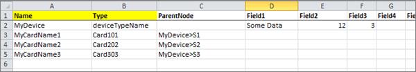
Example of card assignment
Attention!
Make sure the order of appearance of records in the spreadsheet follows the natural hierarchy associated with the objects. For example, if a card will be associated to a specific device, make sure the device was created first. A common mistake is referring to a parent node which has not yet been created. For example:
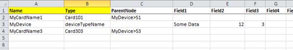
Incorrect import sequence
The first card, ‘MyCardName1’ will not be imported because ‘MyDevice’ has not yet been created.
7.5.2.5 Links
This worksheet is used for creating links in the netTerrain project.
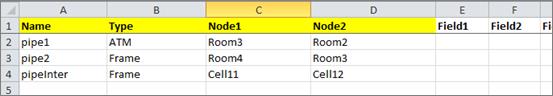
Links worksheet
The columns include:
-
Name: mandatory field that represents the name of the link
-
Type: mandatory field that identifies the type associated with the link. Once a type is defined, the custom fields in the spreadsheet will correspond to the custom fields associated with that node type in the netTerrain catalog
-
Node1: mandatory field identifying the name of the starting node or device.
- Node2: mandatory field identifying the name of the ending node or device
- Field#: the custom fields associated with the type of the link. Each field in the spreadsheet has a sequential number prefix, which corresponds to the order of appearance of the custom field in the netTerrain catalog. For example, Field3 in the spreadsheet will populate the custom field that appears in order #3, for that type, in the netTerrain properties tab (not counting the id, name, type or endpoint fields).
7.5.2.6 Creating links between ports
Sometimes you need to create links between ports. This creates an additional naming convention challenge because ports are usually just named based on their sequential port number. Naturally, in such a case just using the port name to identify endpoints would be a problem since many ports with the same number might exist in the project.
To overcome this, you can identify ports by appending the device ancestry information in both the Node1 and the Node2 columns:
For instance, let’s say we have a device called ‘myDeviceName’ with two ports ‘P1’ and ’P2’ and another one called ‘myOtherDevice’ also with two ports ‘P1’ and ’P2’
To link both ‘P1’ ports together and the ‘P2’ ports together we could format the Node1 and Node2 columns like indicated below:
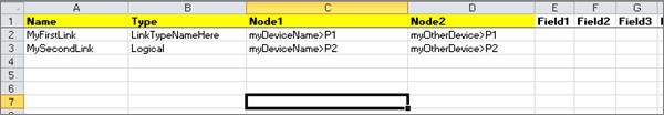
Creating links between ports
In a similar fashion we can embed and concatenate card information in our endpoint columns, such as the example below:

Creating links between ports residing in cards
7.5.3 Troubleshooting and Tips
As you build your import spreadsheet, we recommend testing the import in phases to catch input mistakes early.
When errors occur on input, please refer to the ‘App_data’ in the netTerrain web directory folder. The log files are named as follows: ‘[date time] EI [name of uploaded spreadsheet]’.
Here are some common mistakes and their resolution:
7.5.3.1 Input string not in correct format issue
Below is a typical logged error related to input string problems:
Input string was not in a correct format.

at System.Number.StringToNumber(String str, NumberStyles options, NumberBuffer& number, NumberFormatInfo info, Boolean parseDecimal)

at System.Number.ParseInt32(String s, NumberStyles style, NumberFormatInfo info)

at System.Convert.ToInt32(String value)

at NetTerrain.Importers.ExcelImporter.ExcelTypeToImportFormat(DataRow nodeTypeRow, String nodeTypeName)…
Usually this error stems from two possible data entry mistakes:
1) The Excel import spreadsheet had its structure (the columns) modified. You should make a new copy of the original bulk import spreadsheet and copy over the information.
2) Not all mandatory fields were filled out
7.5.3.2 Type image ignored
You may get the following error in the log:
Make sure that when you are importing node types, you zip together the spreadsheet with a folder called ‘graphics’, which contains all the referenced icons.
7.5.3.3 Parent node missing
You may get the following error in the log:
This one is self-explanatory and usually the resolution is simple. Make sure that the parent node exists or, if it is supposed to be imported during the same process, that it is higher up in the row sequence than the nodes that produce the error.
7.6 PDF export
One of the easiest ways to export diagrams from netTerrain is by using the PDF export option. The PDF option is available from the Import & Export menu in netTerrain. If the PDF icon is not present, then it was not enabled by the administrator (see netTerrain admin guide on how to enable the feature). There is no additional software that needs to be installed for the PDF export option to work.
To use the PDF export, follow these steps:
1) Press the PDF Export button:
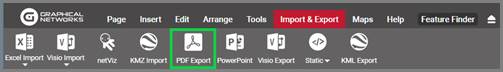
PDF export button
2) A PDF Export options dialog appears
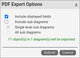
PDF export options
The Include displayed field option will preserve any displayed fields present in the diagrams when exported. The include sub diagrams provides two options:
-
a. Single Level sub diagrams: will export the current diagram and one level below
-
b. All sub diagrams: will export the current diagram and all diagrams below
3) Press ‘Submit’
Attention!
This can be a time-consuming process when several diagrams are part of the export. When performing a large export, it may be best to do this during a time of the day when there is less user activity. For instance, when they are all sleeping or at the water cooler chatting non-stop.
Notice that before hitting submit, netTerrain will provide you with a count of nodes to be exported so that you can decide whether a reduction in number of diagrams to export is in order.
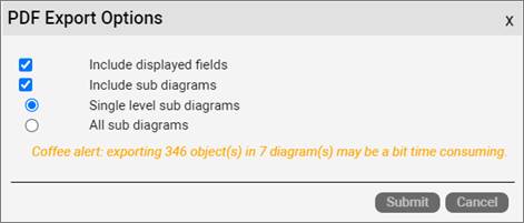
Message indicating the number of nodes and diagrams to export
8 Outside plant
netTerrain OSP is an additional module that turns your netTerrain software into an outside plant (OSP) documentation tool. This requires a separate product license.
netTerrain OSP includes the ability to create dynamic (or georeferenced) maps within a diagram. It also changes the behavior of a diagram in situations like zooming, copying and object placing, compared to diagrams that contain static backgrounds. netTerrain OSP also has some additional features for cable, strand and circuit management not available with regular netTerrain licenses.
netTerrain georeferenced maps use a variety of mapping sources. The default map source includes the OpenStreetMap® repository for cartographic representation of data (from now on OpenStreetMaps or OSM) and Google maps. OSM maps do not require any paid license or service, but certain map views may require an OSM API key.
netTerrain OSP also supports ESRI and other sources which you can set up in the settings.xml file located on the netTerrain server. Our default installation includes paths to 3 OSM layers, Google standard and satellite views.
All these services require a connection to the internet by default; however, you can set up your internal map servers for services such as OSM.
Attention!
The netTerrain OSP module is a licensed product and is not included with netTerrain. For this to work you would need to purchase the OSP module.
Also, for the georeferenced maps to be properly generated, the client machine needs to have a connection to the internet. If this is a problem in your environment, you can create your own internal OSM server. For certain map sources you may need an API key or paid royalty license which may depend on map usage. Contact support for more details.
8.1 Advantages of using georeferenced diagrams
In terms of keeping an inventory of your network, static maps may be all you need, but once you need to document your outside plant, dynamic (or GIS or georeferenced) maps become critical, specifically around the features of zooming and location-based placement.
8.1.1 Large diagrams and deep zooming
As opposed to static maps, which lose resolution and get pixelated as you zoom in, with georeferenced maps you can work with relatively large geographical areas and zoom in until you reach the street or block level without losing precision.
This lets you add a large number of small objects in an extensive map area without losing precision on the geographical details at deep zoom levels
8.1.2 Embedded coordinates
Another benefit of using georeferenced diagrams is the fact that when the map is created, its lat /long coordinates are automatically embedded. As such, users do not have to manually find and enter the appropriate coordinates for a specific map.
Also, coordinates in georeferenced diagrams support 6 decimals of precision, which provides accurate placement of objects down to the street / block level.
Coordinates in georeferenced diagrams are automatically displayed when you load a map. Coordinates are displayed on the lower left corner of the map and change automatically as you move the cursor over the map.
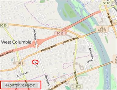
Coordinate display on georeferenced diagrams
8.1.3 Node identification (halos and clusters)
Another nice feature of georeferenced diagrams is the ability to identify the location of any nodes even if you are zoomed too far out to see the actual node icon.
For instance, say we have a georeferenced diagram that covers a large geographical area (such as the state of Maryland) and we want to show buildings at the street level. Those buildings may be drawn to scale at the street level but once we zoom out they would be very small and essentially disappear.
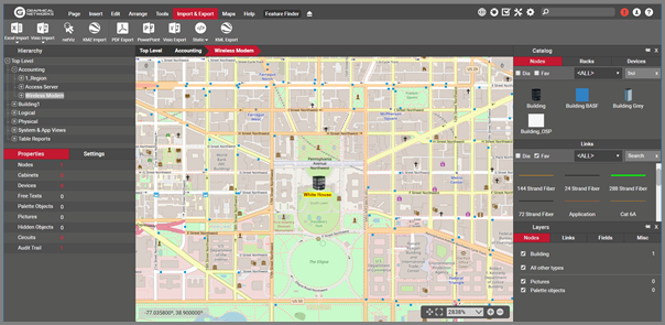
Building on the center is shown at street level
At a certain point, in a static map we would not be able to see them anymore, but within a georeferenced diagram these small objects are aggregated using clusters.
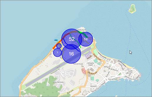
Nodes grouped in clusters
Icons not grouped in a cluster are identified by a marker (a.k.a. halo) that is always displayed with the same size relative to the diagram.
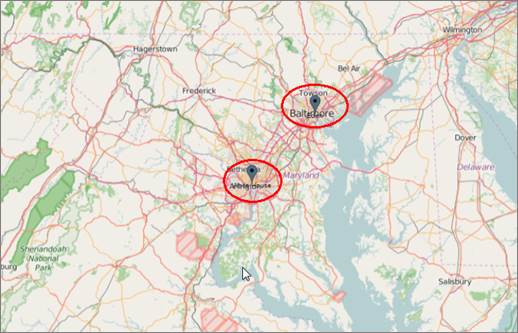
Individual zoomed out buildings represented by markers (halos)
8.1.3.1 Disabling clusters and halos
There are instances where clustering may become a liability. For example, in linear layouts of fiber traversing vast geographical regions the clustering can look weird. There can be other situations where you wish netTerrain didn’t render a set of objects in a cluster or maybe didn’t render halos.
You can disable the clustering, halos, or both. To disable them globally, you need to do it from the settings.xml file, so you may have to ask a netTerrain admin to disable this for you.
You can disable halos on a per-diagram basis from the layers tab->miscellaneous.
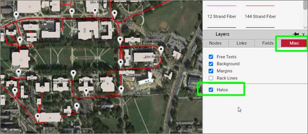
Disabling halos from the layers tab
8.1.4 Cable, strand and circuit management
In netTerrain DCIM or netTerrain logical you can model cables, strands and circuits, but you are essentially doing everything by hand modeling links in the catalog accordingly. There are no specific business rules associated to strand counts in a cable, circuit management and so on. Fiber plant users, however, have a consistent way of managing these, so in netTerrain OSP you have a whole array of extra features to simplify the process of adding, deleting and managing circuits, cables and strands.
Also, circuits in OSP have their own special CLR views, map displays, list reports and more, as we will see later in this chapter.
8.2 Working with map sources
As mentioned earlier, netTerrain georeferenced maps use a variety of mapping sources. The default map source includes the OpenStreetMap® repository for cartographic representation of data (from now on OpenStreetMaps or OSM) and Google maps. OSM maps do not require any paid license or service, but certain map views may require an OSM API key.
netTerrain OSP also supports ESRI and other sources which you can set up in the settings.xml file located on the netTerrain server. Our default installation includes paths to 3 OSM layers, Google standard and satellite views.
All these services require a connection to the internet by default; however, you can set up your internal map servers for services such as OSM.
To set up a new map source or modify an existing one you need access to the netTerrain app server, find the settings.xml file on the root directory, open said file with a text editor, locate the <!-- Sources of map tiles --> tag and carefully edit the information. Consult with your netTerrain administrator or Graphical Networks tech support and how to add other sources or modify these tags.
<!-- Sources of map tiles -->
<add key="MapSource1" value="https://a.tile.openstreetmap.org/{z}/{x}/{y}.png" />
<add key="MapSource2" value="https://a.tile.thunderforest.com/transport/{z}/{x}/{y}.png" />
<add key="MapSource3" value="https://tile-a.openstreetmap.fr/hot/{z}/{x}/{y}.png" />
<add key="MapSource4" value="https://mt.google.com/vt/lyrs=m&x={x}&y={y}&z={z}" />
<add key="MapSource5" value="https://mt.google.com/vt/lyrs=s&x={x}&y={y}&z={z}" />
<add key="MapSource6" value="" />
Map sources in the settings.xml file
From the project, you can switch from, say, an OSM view to a Google maps view for any given diagram by simply right-clicking on the diagram and choosing the source.
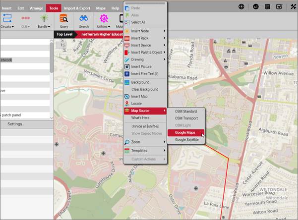
Additional OSP sources
8.3 OpenStreetMap (OSM) maps
netTerrain can use the OpenStreetMap cartography for its GIS maps. The OpenStreetMap Foundation is a non-profit foundation whose aim is to support and enable the development of freely-reusable geospatial data maps. It is a collaborative project to create a free editable set of maps of the world.
OSM maps can be used in any diagram to overlay any netTerrain objects on top of it. These maps are royalty free and users can render as many maps as needed in netTerrain.
8.3.1 Map layers
The OSM integration with netTerrain includes 3 different map layers, which can be switched at any time. Layers provide the user with the ability to change the background look and feel of maps. For example, in certain instances it may be desirable to use a less cluttered map layer to improve the visibility of the netTerrain objects on top of it.
8.3.1.1 Standard layer
The standard layer is the default tile layer. It is also the layer that provides most of the map level symbols. Single symbols denote several kinds of points of interest or describe a larger area. If the map feature in question has a name, it is written below the symbol most of the time, in the same color of the symbol.
For more information about the standard please visit the following web page: http://wiki.openstreetmap.org/wiki/Standard_tile_layer
8.3.1.1.1 Standard layer symbols
The following table shows example of symbols used in the standard layer tiles:
| Symbol | Description | Category |
|---|---|---|
 |
Bar | Sustenance |
 |
Cafe | Sustenance |
 |
Restaurant or food court | Sustenance |
 |
Library | Culture/entertainment |
 |
Museum | Culture/entertainment |
 |
Playground | Leisure |
 |
Water park | Leisure |
 |
Campsite, campground | Outdoor |
 |
Point of information, such as a tourist information office, informational board, map board, etc. | Tourism |
 |
Hotel | Tourism |
 |
ATM or cash point | Financial |
 |
Bank | Financial |
 |
Hospital | Healthcare |
 |
Pharmacy | Healthcare |
 |
Electricity pylon | Electricity |
 |
Small electricity pole | Electricity |
 |
Post box | Communication |
 |
Post office | Communication |
 |
Fire station | Fire station |
 |
Rent a car | Transportation |
 |
Car parking lot or other facility to park cars | Transportation |
 |
Gas station or petrol station or similar | Transportation |
 |
Bus stop | Transportation |
 |
Railway station, railway stop point or tram stop point | Transportation |
 |
Airport | Transportation |
 |
Traffic lights | Road features |
 |
Railway crossing | Road features |
 |
Peak, summit, etc. | Nature |
 |
Tree | Nature |
 |
Town hall | Governmental institutions |
 |
Police station | Governmental institutions |
 |
Embassy | Governmental institutions |
 |
Christian | Religious place |
 |
Jewish | Religious place |
 |
Muslim | Religious place |
 |
Hindu | Religious place |
 |
Bakery | Shop |
 |
Supermarket | Shop |
 |
Book store | Shop |
8.3.1.1.2 Standard layer lines
In OpenStreetMap, the major roads of a road network are sorted on an importance scale, from motorway to quaternary road. The following table shows example of lines used in the standard layer tiles:
| Symbol | Description | Category |
|---|---|---|
 |
Motorway, the most important roads in a road network. Equivalent to freeway, Autobahn (Germany), etc. | Major road |
 |
Trunks, the most important roads in a road network that aren't motorways. | Major road |
 |
Primary road | Major road |
 |
Secondary road | Major road |
 |
Tertiary road | Major road |
 |
Quaternary road | Major road |
|
Residential road | City road |
 |
Access road (may be also outside of a city) | City road |
 |
Living street | City road |
 |
Pedestrian street | City road |
 |
Bridleway | Non-motorized |
 |
Cycleway | Non-motorized |
 |
Footway | Non-motorized |
|
Non-specific path (footway, cycleway or bridleway) | Non-motorized |
 |
Steps | Non-motorized |
8.3.1.1.3 Standard layer areas
Areas in the Standard tile layer denote various things, from land usage to buildings to restricted access zones.
The following table shows example of areas used in the standard layer tiles:
| Area | Description | Category |
|---|---|---|
 |
Land (This is only shown when no more specific information is available) | Nature |
 |
Body of water (ocean, sea, pond, river, swimming pool, etc.) | Nature |
 |
Natural grassland | Nature |
 |
Bushes and small trees | Nature |
 |
Beach | Nature |
 |
Wetland | Nature |
 |
Residential area | City planning |
 |
Commercial area or business park (predominantly offices) | City planning |
 |
Retail area (predominantly shops) | City planning |
 |
Industrial area or area for railway usage | City planning |
 |
Non-specific building | Buildings |
 |
Airport terminal | Buildings |
 |
Farmland | Agriculture and industry |
 |
Park | Leisure |
 |
Tourist attraction | Leisure |
 |
Land used by the military. | Military |
8.3.1.1.4 Other layers
In addition to the standard layer, netTerrain can render OSM diagrams in 2 other styles:
- Transport: these maps mainly show railways, streets, highways and other routes without much regard for other map details. This is a great layer where you want less cluttered maps. the only drawback with this layer is that it shows a watermark unless you get a license key for its use (some licenses for the transport layer can be obtained for free).
- Light: maps where the colors are light to make it easier to see objects placed in the map.
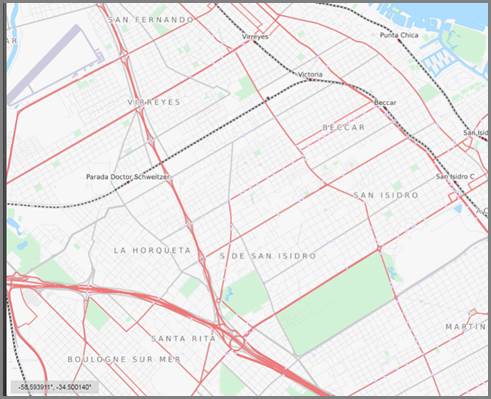
Transport layer map
8.4 Adding georeferenced maps to your diagram
To add an georeferenced map right-click on the diagram and choose ‘Map’ (or alternatively click on the Map button in the Maps menu):
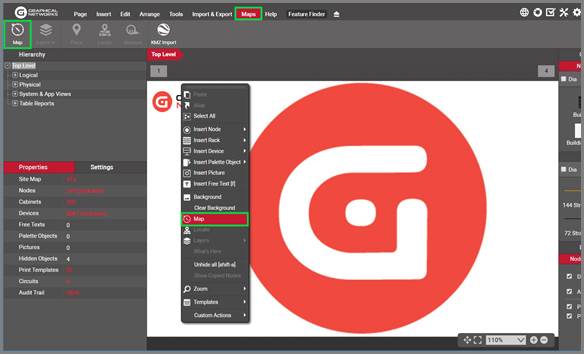
Map Specifications
A dialog with a map previewer allows you to easily zoom in on a location to use. You can utilize a very large geographical area, or even the whole world in a single netTerrain diagram but try to choose as small an area as possible that is relevant to the diagram you are working with to maximize performance and take advantage of hierarchical diagrams in netTerrain.
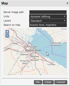
Map previewer
The options for the Map Specifications are as follows:
- Server Image Path: If there is a background image in use it will provide the image path details.
- Units: Change this to dynamic lat/long to use the dynamic maps.
- Map Layers: these layers are discussed in the previous section
- Search on Map: Type in the street, city or other location information to find a specific map location.
Once you found the desired map with its appropriate zoom level, simply click ‘Ok’ and the map will be rendered on the page accordingly.
8.4.1 Use of maps covering large geographical areas
As mentioned above, you can utilize a very large geographical area, or even the whole world in a single netTerrain diagram, but if you use a large geographical area instead of taking advantage of parent-to-child diagrams you may tend to place a large number of objects in one diagram, which decreases performance
You should not use georeferenced diagrams as a replacement for drill down capabilities. As such, whenever applicable, it is recommended to structure your project in collections of parent-to-child diagrams.
8.5 Working with georeferenced diagrams
Georeferenced diagrams allow the placement of any netTerrain objects, and these behave pretty much like objects on standard static backgrounds except for a few differences, which arise all due to the fact that it is highly likely that in georeferenced diagrams users will resize nodes to very small size so that they are properly represented to scale:
-
zoomed out nodes that are too small to see may be aggregated in clusters or display markers or halos, as discussed previously in this chapter
-
When adding a node in a georeferenced diagram, the default size is relative to the zoom level
-
Link thickness does not increase as you zoom in. The thickness is relative to the zoom level
8.5.1 Placing nodes on georeferenced diagrams
The placement of nodes in georeferenced diagrams is similar to placing them on any regular netTerrain diagram. There are still a few details that need to be considered.
For example, if you are using a map covering a wide geographical area and you want the nodes to be drawn to scale (for example at the street level) it becomes very impractical to add the node when you are zoomed out and then resize it because you may need several processes of resizing, zooming and panning in order to accomplish the task.
Instead use the following approach: zoom in to the desired level first, then drag and drop the object from the catalog to the diagram or right-click on the location (for instance the exact street corner) where you want the node placed, and then insert the node. As mentioned earlier, you will notice that the default size of the node is relative to the zoom level (in a static map, if you zoom in heavily, the default size of the node may be such that the rendering in the zoom out state ends up drawing a huge node).
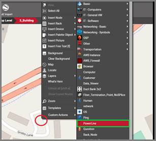
Inserting a node on a zoomed-in area
If you are copying and pasting a node, it is also convenient to paste the copied node by right-clicking on the zoomed in area and on the exact place, using the diagram context menu in order to minimize any additional resizing and panning actions.
8.5.1.1 Placing nodes based on location or GIS coordinates
It is also possible to place nodes in georeferenced diagrams based on GIS coordinates or location. Click on the node and then on the ‘Place’ button (Maps menu) or right-click on the node and press ‘Place’.
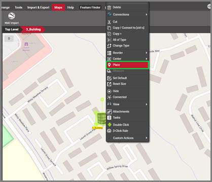
Placing a node by location or lat/long
This will open a dialog box where you can either search for a location and even limit that search to the zoomed in area or you can also type in the lat and long coordinates.
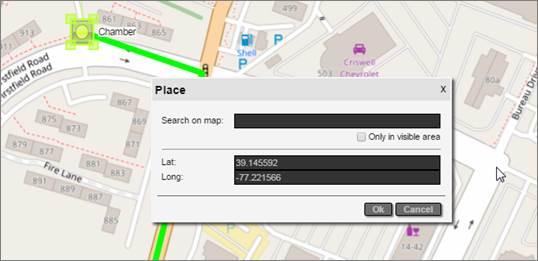
GIS and location-based placement
If the lat/long values are malformed or outside the boundaries of the map on the diagram, you will see a notification prompting you to fix that mistake, such as the ‘coordinate out of bounds’ message seen below:
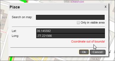
Coordinate out of bounds
Once you click ‘Ok’ netTerrain places the node and pans/zooms to the appropriate area on the map.
8.5.1.2 Measurements in georeferenced diagrams
Measurements in georeferenced diagrams are essentially the same as in static maps with embedded coordinates. Since coordinates are automatically associated with georeferenced diagrams, users can always measure the distance between two nodes or measure the length of a link in miles, based on the auto embedded coordinates. We’ll review the measurement process here again.
To measure the distance between two nodes, do the following:
1) Select the two nodes
2) Right-click on one of them and select the menu ‘Measure’ option (or click on the Measure button in the Maps menu)
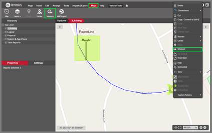
3) This will bring a pop-up dialog showing the distance (as the crow flies)
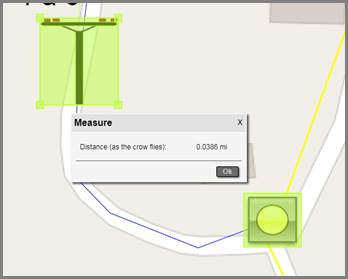
Example of measuring distance between two nodes in miles
To measure the length of a link, do the following:
1) Right-click on one of them and select the menu ‘Measure’ option (or click on the Measure button in the Maps menu)
2) The pop-up dialog will now show the length
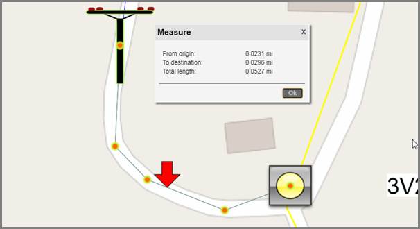
Example of measuring the length of a link in OSM diagrams
Notice the red arrow pointing to the link. This is the location where you right-clicked, and the distance to the origin and destination are taken from that exact point where the mouse-click happened. Of course, this only applies if you used the right click method to measure the length. This feature could be useful in fiber measurement situations to find out the distance of a fiber cut to the nearest manhole or location of a certain connection point to the destination.
Also notice how link measurements consider the bend points! This is especially useful for outside plant purposes when measuring total lengths of links with several bend points.
Attention!
When measuring lengths of links with bend points, the actual position of the bend point is what matters. For straight links this provides an exact measurement, but for curved links the actual path of the link will not coincide with the measured number since the bend points in Bezier curves lie outside of the line.
8.5.2 Creating links and bend points
The process of creating links and bend points in georeferenced diagrams is not different than in other diagrams, except for how the links look when zooming in or out. We will only review the drag and drop method for creating links:
1) Move the mouse to the link catalog pane and select a link type by clicking on the left mouse button
2) Drag the mouse cursor to the starting node and the diagram
3) As you hover the mouse over the starting node, the node should display 9 red snapping points (more on that later)
4) Once you identified the desired connection point on the starting node, release the left mouse button and drag the mouse cursor to the endpoint
5) Once you hover the mouse over the ending node, the node should also display 8 red snapping points
6) Once you identified the desired connection point on the ending node, press the left mouse button and the link is created!
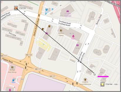
Creating a link using the drag and drop method
After the link is created, notice that when you zoom in or out of the map, the link thickness always remains the same regardless of zoom level. This is in contrast with diagrams not using dynamic maps, where the thickness of the link is absolute.
8.5.2.1 Creating multiple bend points quickly using the ‘b’ shortcut
As we saw before, a very quick way of adding multiple bend points and directing the path of the link is to use the ‘b’ shortcut. Select the link of interest first and then press and hold ‘b’. Move your mouse to the position of where you want to add a bend point and press the left mouse button. This will add the bend point where you click on the screen.
You can perform this operation as many times as you want in succession.
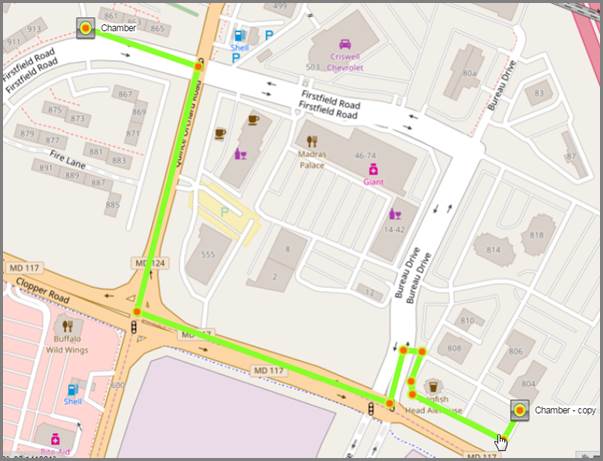
Conduit following a complex path using bend points
8.5.3 Location searches
Georeferenced diagrams in netTerrain allow for location-based searches. For instance, you can enter a street number and find the precise location on a map. To do that simply right-click on the diagram (or press the ‘o’ key):
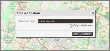
Finding a location in a georeferenced diagram
The search is smart in many ways:
1) It only looks for locations within the map displayed on the diagram, not the whole world
2) It shows any matches as you type
3) It can restrict the search for places that are inside the visible zoomed-in area, by clicking on the ‘Only in visible area’ option
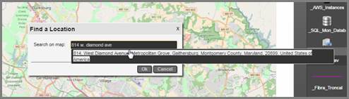
Finding a match
Once one or more matches are found, you can click on the appropriate entry and netTerrain will auto pan and zoom to the resulting location. netTerrain will also add a green marker to the corresponding location.
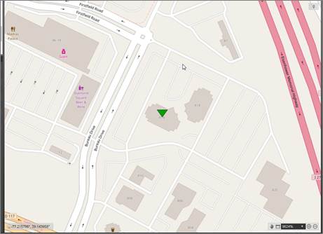
Found location
8.6 Typical Outside Plant (OSP) elements
The netTerrain catalog is the place where power users or administrators can create and manage netTerrain types, including nodes, devices, racks, cards, links as well as Outside Plant objects.
The netTerrain catalog already includes several prepopulated OSP elements. As we know, any user with Power User rights can easily extend the catalog to include more custom types, in minutes. The details about catalog management are covered at length in the Power User guide, so it may seem a bit redundant to talk about types already included in the catalog when it is so easy to add new ones. However, it is worth highlighting some of the existing types and use cases that specifically apply to OSP.
8.6.1 OSP Node Types
netTerrain version 7 includes several OSP node types that can be used for outside plant functions such as containers of OSP devices or connection points for OSP links.
To view the built-in node types included in a new installation of netTerrain, click on the OSP category in the node catalog, as depicted below:
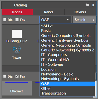
Pre-built OSP node types in the netTerrain catalog
The current list of predefined types in the node catalog includes the following objects:
-
Manhole
-
Handhole
-
Slack
-
Tower
-
Antenna
-
Pole
-
Mast
-
Satellite
Not included in this list are elements such as buildings, sites, regions, generic connection points, networks and other containers that, while part of many OSP projects, are also used in other contexts, and, as such, aren’t specifically categorized in the OSP catalog folder.
The following is the expanded list of OSP objects, as seen in the node catalog:
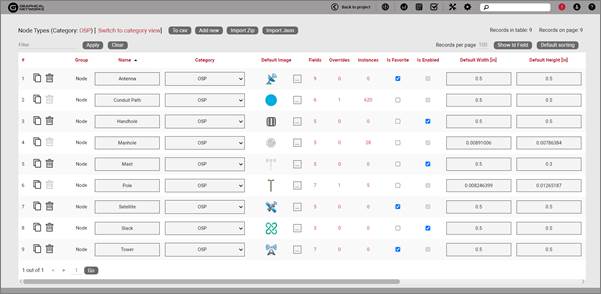
OSP node catalog
The custom fields included for each predefined object vary from node type to node type. As an example, we show the list if fields for the object “manhole”:
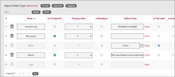
List of fields for the “Manhole” type
As mentioned above, we expect your specific Outside Plant project to have other types in the catalog, which, as you can see from the power user guide, is trivially simple to expand. It takes maybe a couple of minutes to add a brand new object type, including its properties and behaviors.
8.6.2 OSP Link Types
netTerrain version 7 includes several OSP link types that can be used for outside plant functions such as trenches, conduits, ducts and more.
To view the built-in node types included in a new installation of netTerrain, click on the OSP category in the node catalog, as depicted below:
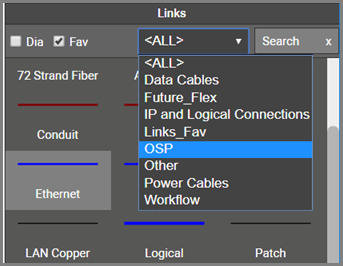
Pre-built OSP link types in the netTerrain catalog
The current list of predefined types in the node catalog includes the following objects:
-
Conduit
-
Duct
-
Overhead Line
-
Trench
-
Wireless Link
The following is the expanded list of OSP objects, as seen in the link catalog:
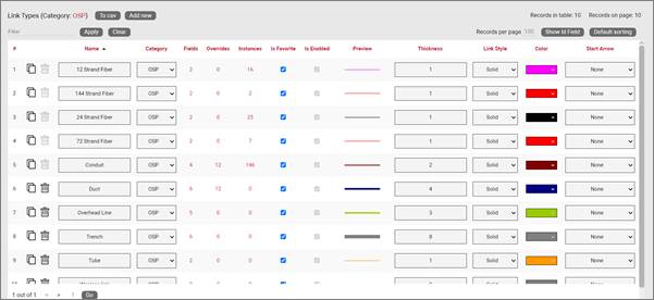
OSP link catalog
The custom fields included for each predefined object vary from link type to link type.
As mentioned above, we expect your specific Outside Plant project to have other types in the catalog, which, as you can see from the power user guide, is trivially simple to expand. It takes maybe a couple of minutes to add a brand new object type, including its properties and behaviors.
8.6.2.1 Circuits and strands
Circuits and strands can be modeled as regular links in the catalog, but as we will see later in this chapter, it is more convenient to use the built-in entities that already exist in netTerrain for this purpose.
8.6.3 OSP Device Types
netTerrain version 7 also includes several OSP device types that can be used for outside plant functions, mainly related to fiber strand management and splicing involving outside plant equipment. As opposed to node and link types, which lend themselves to having its own special OSP category, the OSP device types are spread across the catalog by vendor, so there isn’t an OSP category per-se.
To find a specific OSP device type you would typically search it by value. For example, you may want to look for a splitter in the catalog and type the string “split” and get the following result:
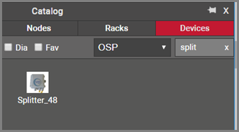
Pre-built OSP link types in the netTerrain catalog
In addition to splitters, you can find a variety of other device types in the catalog, including splices, enclosures, fiber panels, distribution panels and much more.
Just as with node and link types, the custom fields for each OSP device type vary from case to case and can be easily customized by a power user. As an example, we show the list of fields for the object “Splice enclosure”:
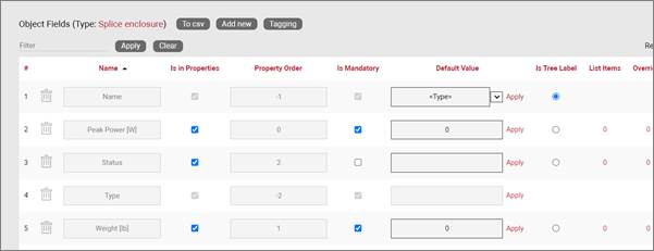
List of fields for the “Splice Enclosure” device type
Notice that OSP device types behave like other (inside plant or DCIM) types: they can cointain slots, ports, and default environmental and physical parameters. In particular, when working with fiber strands that need to be tracked on a strand by strand basis down to the connection point level we recommend modeling the equipment as netTerrain devices and model each connection point as a port.
Also, as mentioned before, we expect your specific Outside Plant project to have other types in the catalog, which, as you can see from the power user guide, is simple to expand. You can model new OSP device types yourself or request from us at no extra charge when you are under maintenance.
8.6.4 Use case 1: modeling a GPON network
Without pretending to be thorough in our coverage, we would like to showcase a typical OSP diagram with some of its elements using a GPON network as an example.
In a GPON network you will probably find node types, device types and, of course, link types. Below, we review some examples of node, device and link types that can be typically found in GPON deployments.
8.6.4.1 GPON Node Types
You typically want to model containers of devices and connection points for fiber trunks, ducts or conduits as nodes. These are the objects that will be laid out on a map. Examples include:
-
Underground demarcation points, such as manholes and handholes, which typically contain enclosures or splices, which in turn will serve as connection points for fiber strands
-
Nodes that serve as connection points for overhead lines and equipment, such as poles and masts
-
Buildings and remote sites that contain inside plant equipment
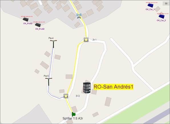
Remote area coverage with typical GPON node types
8.6.4.2 GPON Device and link types
In GPON deployments we will typically find:
-
Enclosures and splices
-
Splitters of several orders (1 to 2, 1 to 4, 1 to 8, 1 to 16, etc.)
-
Inside plant equipment like fiber panels and fiber distribution equipment
-
Customer equipment such as ONTs and much more
Customer equipment and inside plant equipment can be rack mounted and modeled like any other device type in netTerrain. Splitters are usually laid inside manholes or associated with some node type like a pole or building. Usually the last splitter in a chain will connect to the customer equipment. In netTerrain it is easy to associate a splitter with the ONTs (ore relevant customer equipment) and can be easily filtered out on a diagram:
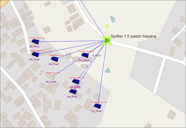
View of a splitter on a maop and related customer devices
We recommend modeling the splitter so that when you double click on it you can see the incoming strand and the demultiplexing fiber strands, as depicted below:
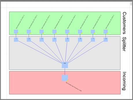
Splitter connectivity view showing individual strands
Enclosures in netTerrain can be modeled with detail, including buffers (modeled as cards) which, in turn, contain the connection points for the fiber that enters the enclosure, exits it or splits out to cover a subarea (maybe via splitters of several orders).
Each buffer can be color coded by default and contain 12, 24 or whatever number of connection points for the incoming, outgoing and derived strands.
8.6.5 Use case 2: Outside to inside plant fiber tracing
Once the outside plant and inside plant elements are laid out, you can trace each individual strand from the outside plant end user equipment to the inside plant port. This trace will show the entire path, including any intermediate devices and connection points (splitters, splices, enclosures, etc.).
To trace the fiber strand simply launch a Circuit Layout Record (CLR), by double clicking on the strand or right clicking on the associated port/connection point.
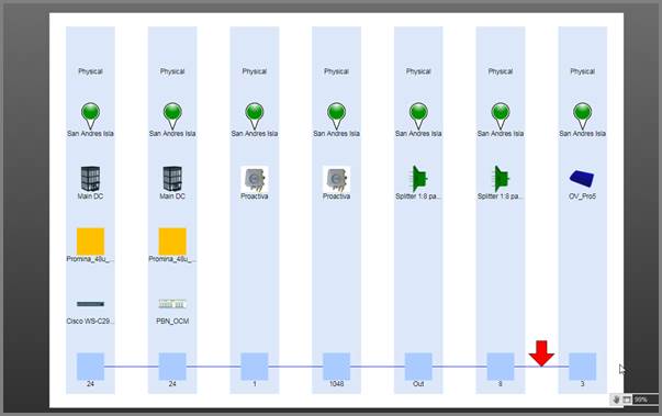
CLR tracing of a single strand
8.6.6 Use case 3: Wireless networks and link budget calculation
netTerrain is the ideal choice for depicting wireless networks on georeferenced maps. There really isn’t a difference, from a hierarchy and rendering point of view in how those networks are treated versus some of the other topologies.
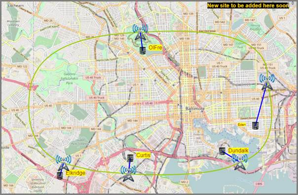
Sample regional wireless networks overview
Typical wireless types found in the netTerrain catalog include towers, antennas of different kinds, radio equipment, microwave devices and much more. As mentioned before, we expect your specific Outside Plant project to have other types in the catalog, which, as you can see from the power user guide, is simple to expand. You can model new wireless device types yourself or request from us at no extra charge when you are under maintenance.
Wireless networks can be aliased so that the geographical representation of wireless nodes and devices is replicated on logical views of the network, such as the example below:
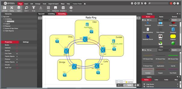
Logical representation of a wireless network
One interesting point about wireless networks (and fiber networks) is the link budget calculation for a given link or chain of links. Using a custom expression, you can associate a field (such as link budget) to a node and, for example, read the value from a CLR view (or any part of the map). In the screenshot below, we can read the dB Loss from the originating link in the chain:
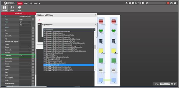
dB loss calculation using a custom function in a CLR
8.7 Working with KML / KMZ maps
If you already have outside plant data in Google earth or another tool that supports exports to KML or KMZ formats, you can leverage that data by bringing it into netTerrain with a few clicks. You can also do the opposite: take a netTerrain georeferenced diagram and export it to KML.
KML and it’s a cousin, KMZ (zipped KML) are typical formats used by mapping or GIS applications, such as Google Earth, and they can be easily imported into netTerrain. KML/KMZ imports and exports are mostly used in the context of a netTerrain OSP project, specifically to import data that exists in another OSP type application and minimize manual data entry or to export the netTerrain data and consume it inside an application that supports KML.
Nothing needs to be setup on the netTerrain server or on the client side to make this work but note that the KML import and exports buttons only work for netTerrain diagrams containing a dynamic map. Dynamic maps are only available with a valid netTerrain OSP license.
8.7.1 Prerequisites for importing KML / KMZ files
As stated, a KMZ file is basically a compressed version of a KML file, but there is, however, an important distinction to make: KMZ files can contain images, typically located under a “files” folder. These images would not be present in the KML file since the latter is essentially a text file with a special XML style format.
netTerrain can use images contained in the KMZ file and associate them with the corresponding nodes that are imported. If you want to preserve the same icons used in your application that exported the data, you may want to utilize the raw KMZ format instead of the unzipped KML file and make sure that those images are indeed included. From now, we will mostly just refer to KMZ files, when explaining this feature.
Before importing a KMZ file into netTerrain, make sure that you are on a diagram in netTerrain that already has a dynamic map in it.
This map should ideally be large enough to correctly place all nodes that exist in the KMZ file. This means that every latitude and longitude coordinate associated with a node in the file should be contained within the boundaries of your netTerrain map, otherwise, any nodes falling outside of the boundaries will be discarded. Since importing the data is easy, if your original map is not correct, you can delete the imported data, change the map, and retry. Also, it is better to err on the side of a larger than needed map. You can change it to a smaller map later, and netTerrain will preserve the coordinates (if they are still within the boundaries of the smaller map).
Note
Since KMZ data is flat in nature, netTerrain will not produce any hierarchy of any kind. As such, all the data will be placed in one diagram, which in some cases may produce a very large diagram that takes a long time to load. You can take advantage of netTerrain’s hierarchical nature by using different maps or diagrams, even in a parent to child relationship. To do that, it is better if the source is somehow partitioned so that you can already bring in the data as different KMZ files.
8.7.2 Importing a KMZ/KML file
To import a KMZ file navigate to the diagram that contains the map that will hold the KMZ data and click on the import from KMZ button found under the Import & Export ribbon.
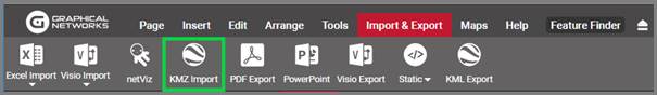
KMZ import button
In the upload KML / KMZ file dialog navigate to the folder that has the KMZ file and click on ‘Start Upload’. Once the import finished, an “Import completed” dialog appears. After you click on ‘Ok’ the map is refreshed, containing the KMZ data.

Sample KMZ import into netTerrain
A few things to note about the results you see after the import:
-
Nodes are automatically assigned a type
-
The same icon you used in Google Earth (or your original tool) should be seen in netTerrain
-
Lat long positioning is, as expected, automated
-
Lines should include bend points to follow the same path you used in the source
-
Line colors should be preserved
-
“Dangling” links are not supported, as such, netTerrain creates fictitious, transparent endpoints to represent these lines
8.7.3 Exporting a diagram to KMZ
To export a diagram to KMZ navigate to the netTerrain diagram that contains the data to export. Remember, it must be a diagram that contains an GIS map.
Then click on the Import & Export ribbon and click on the KMZ Export button on the right.
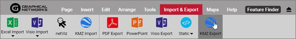
KMZ export button
In the upload KML / KMZ file dialog navigate to the folder that has the KMZ file and click on ‘Start Upload’. Once the import finished, an “Import completed” dialog appears. After you click on ‘Ok’ the map is refreshed, containing the KMZ data.
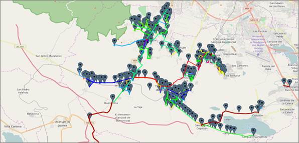
Sample KMZ import into netTerrain
A few things to note about the results you see after the import:
-
Nodes are automatically assigned a type
-
The same icon you used in Google Earth (or your original tool) should be seen in netTerrain
-
Lat long positioning is, as expected, automated
-
Lines should include bend points to follow the same path you used in the source
-
Line colors should be preserved
-
“Dangling” links are not supported, as such, netTerrain creates fictitious, transparent endpoints to represent these lines
8.8 Working with cables and strands
Links in netTerrain so far have been quite simplistic in terms of how they are modeled: choose a look and feel for the link, assign some properties and, if needed, apply some rules (visual overrides) to some of those properties. This works well for virtually all network mapping and most Data Center Infrastructure Management (DCIM) scenarios. In outside plant (OSP) applications, however, a lot of the work with links deals with fiber cables, which contain so-called strands. Due to the high number of strands that can exist in a fiber plant project, and the fact that the strands count, as we will see later, is predetermined based on the type of cable, a different approach is needed.
In the following paragraphs we will see how you can model cables and strands in more efficient ways. We will also be referring to cables as containers of fiber strands even though a cable in netTerrain is still essentially a link. In that sense, link and cable are used interchangeably.
8.8.1 Fiber cable and strand types
Before we dig deeper into how netTerrain models cables let’s review some of the basics of fiber optic cabling. An optical fiber cable is an assembly containing one or more small optical fiber strands that transmit information by means of light signals with certain wavelengths.
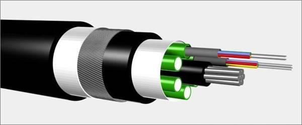
Multi-fiber cable representation
A fiber cable usually has a series of layers for protection and improved performance, with the strands being inside the cable, sometimes also organized in ribbons. There are myriad of different strand counts available in the market, from a couple of strands per cable to up to an 864-count, consisting of 36 ribbons containing 24 strands of fiber each. Some of the most common strand counts are 12, 24, 72 or 144.
In netTerrain a user would want to ideally have these strands created automatically when adding a cable in a fiber plant project. You see this type of automatic creation of subcomponents already, when it comes to hardware: in netTerrain, a device may already have a predefined number of slots and a card, a predefined number of ports. Likewise, a power user can create a link type in the netTerrain that is configured as containing strands, as depicted in the image below.
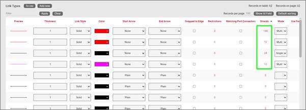
List of cables and their number of predefined strands as seen in the catalog
As an end-user, you can take one of these cables that are defined in the catalog as containing strands, apply them to your project, and they will automatically then create these strands.
For high strand counts or cables with bundles (or buffers) of 12 strands it is common to identify each strand with a color code standard adopted from the early TIA telephone standards for copper wire, as shown in the table below.
| Fiber Number | Color |
|---|---|
| 1 | Blue |
| 2 | Orange |
| 3 | Green |
| 4 | Brown |
| 5 | Slate |
| 6 | White |
| 7 | Red |
| 8 | Black |
| 9 | Yellow |
| 10 | Violet |
| 11 | Rose |
| 12 | Aqua |
The netTerrain catalog supports the TIA standard for the creation of strands in cables by automatically creating sets of 12 strands with the color code shown above. These colors can be overwritten on a strand-by-strand basis.
While cables are just like in the netTerrain catalog with some extra sizzle, strands in netTerrain are not really links. You don’t see them graphically, and they are not individually modeled in the catalog. Just like we do with ports where there is only one system type called port, in the netTerrain catalog there is a system type called ‘strand’. As with ports, a power user can assign custom fields to the strand system type.
8.8.2 Managing strands
Adding a cable with strands to your fiber plant diagram is like adding any regular link. For example, you can drag and drop it from the catalog into the project by connecting it to the endpoints. Once created, the cable will list all its strands in the properties window as a clickable hyperlink:
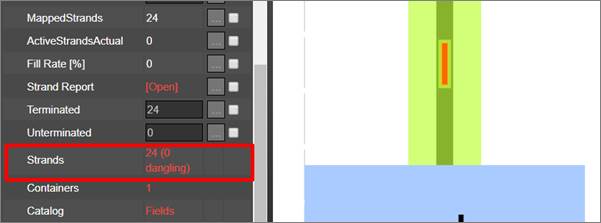
Strands displayed in the cable properties window
The clickable Strands hyperlink opens a new list view that lets you manage the strands. This list view includes several properties and actions to help you manage strand usage, attributes and capacity:
- Buffer color: this is the first square on the left and represents the color of the buffer that contains the strand
- Strand color
- Checkbox to exclude the strand from an ACRA process (more on that later)
- Strand connection utility (see below)
- Strand status
- Strand mode
- Strand name
- Circuit associated to the strand
- Custom fields
Each strand name inherits the predefined name for the strand assigned for that cable type in the catalog.
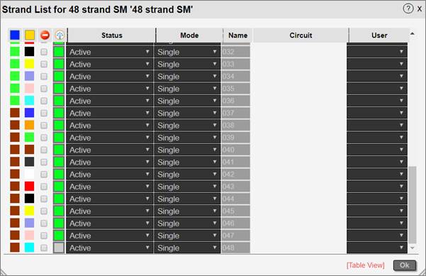
Strand list dialog
Right after the cable is created in netTerrain, all the strands that are contained in it, are disconnected (or dangling), which means that each individual strand will not be connected to any port. Once you start connecting strands to ports, the connected ones will have a lime-colored square to the left of the status field. Any disconnected ones will show a grey-colored square.
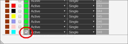
A disconnected strand
8.8.2.1 Connecting strands
To connect a strand to an endpoint or switch the current endpoints, simply click on the grey button, which opens another dialog to manage these endpoints:
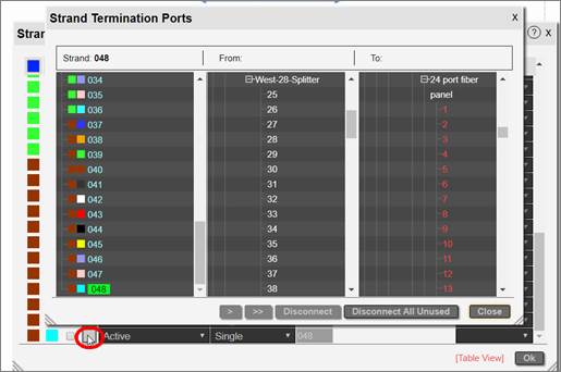
Strand endpoint management
The Strand Termination Ports dialog has three main sections:
- Strand list: includes the strand number with its buffer and strand color
- From termination port
- To termination port
Any connected strands will be displayed in light blue. Disconnected strands will be shown in grey.
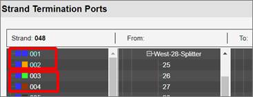
Two connected strands and two disconnected strands
To know how a strand is connected, simply click on it. If it is connected to any ports, these will be highlighted in green:
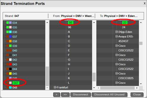
A connected strand
Before connecting a strand to a port, you can inspect any of the ports on the 2nd and 3rd columns by clicking on the port name. This will open a new tab and navigate to the netTerrain project and highlight the port.
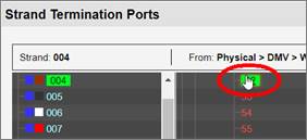
Navigating to a port
If you want to connect a strand, you can do that individually by clicking on the strand and simply selecting the ports on the 2nd and 3rd column. Notice that these columns display the full netTerrain hierarchy.
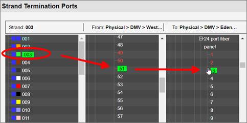
Connecting a strand individually
You can automatically connect the next strand on the sequence, by clicking on the ‘>’ button. This will connect the next strand to the next available ports sequentially.
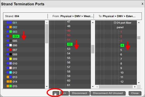
Sequentially connecting strands with the single arrow button
You can also connect the entire batch of unconnected strands following the selected one, by clicking on the ‘>>’ button. This will connect strands if the corresponding consecutive ports are also available.
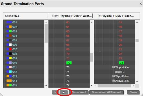
Connecting a batch of strands with the '>>' button
Once the strands are connected to endpoints, the endpoint indicator in the strand list is shown in green.
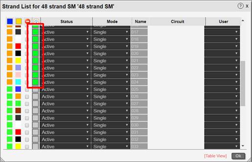
Terminated strands
It is important to have your strands terminated, otherwise they cannot be used for circuits (more on that later).
8.8.2.2 Disconnecting strands
If you wish to disconnect a strand, select it and then click on the disconnect button. You can also disconnect all strands that are not currently in use by a circuit if you click on the ‘Disconnect All Unused’ button.
8.8.2.3 Strand table view
You can open a table view of all the strands on a cable by clicking on the ‘Table View’ hyperlink located on the bottom right corner of the strand list dialog.
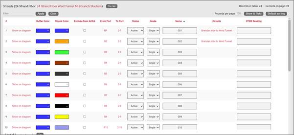
Strand table view
8.8.2.4 Strand colors on ports
As soon as a port is used for a strand, you can visually see that the ports is already “taken” by means of a strand indicator. This indicator consists of a small circle rendered inside the port icon showing the strand color. The circle can be configured by an administrator (in the web.config file) to be displayed on the bottom, center or bottom right of the port icon.
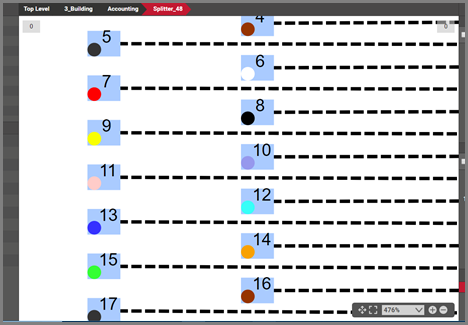
Strand indicators
You can double click on any port with a strand to get to the other end of the strand. netTerrain will then automatically navigate to the diagram that contains the port where the other strand endpoint is connected and highlight it.
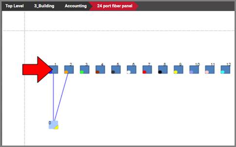
Highlighted port of opposite endpoint of a strand
When clicking on a port that has a strand connected to it, that port will include some basic information about that strand, as shown below:
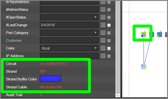
Strand information for port
The strand information includes:
- Circuit link: opens the circuits table with that particular circuit filtered out
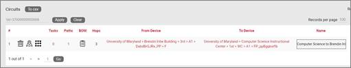
- Strand number link: opens the strand list showing that particular strand
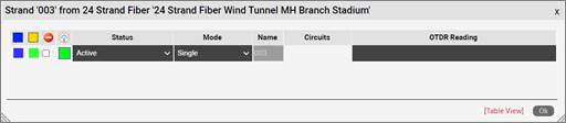
- Strand buffer color: color of the buffer containing the strand
- Strand cable link: takes you to the diagram that contains the cable containing the strand
You can open the strand dialog from a port as well by clicking on the port and then clicking on the Strand number hyperlink:
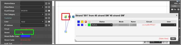
8.8.2.5 Strand custom fields
Strands can also have custom fields, which are defined in the catalog (see Power-User Guide). Users can edit strand property values for each strand from the strand list as well. Custom fields appear after the circuit list and can use text fields as well as combo boxes.
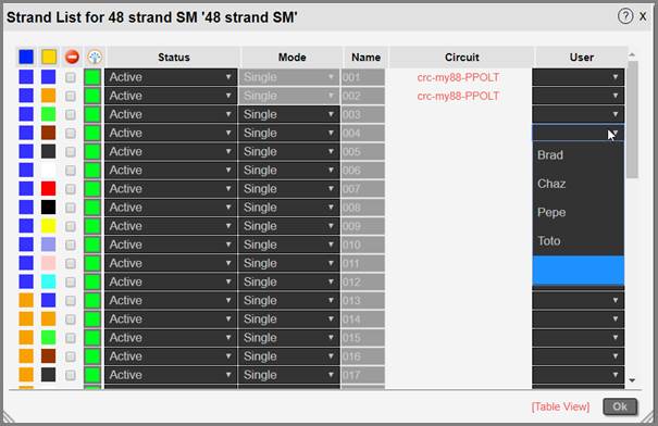
Strand custom properties displayed in the strand list
Strand custom fields are searchable just like any other property in netTerrain:
1) Follow the usual process for searching by typing in a string in any of the netTerrain search boxes
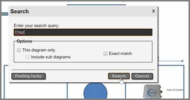
2) From the search results, click on the entry that you are interested in (let’s assume it corresponds to a strand custom field value)
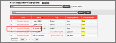
3) The strand that contains the custom field value will be highlighted in the newly opened strand list dialog
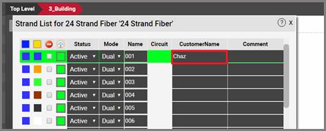
8.8.2.6 Resplicing
In some cases uses may need to insert a new splicing object in between an existing cable with strands or container of cables with strands. Normally this would mean reconnecting all the existing strands and more. This could be a bit of a nightmare. An easier way is to use the resplicing feature.
This feature can be used in two ways: selecting a node to resplice the link or adding a new node in between.
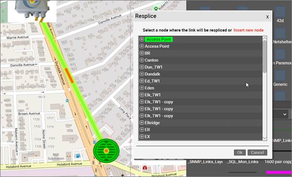
Resplicing a link
If you click on the 'Insert new node' option on the top right, you can then choose a splicing node that will be inserted between the endpoints of the selected link and all strands will be reconnected (terminated) automatically.
You can also splice out individual strands. A fiber cable with strands can be spliced without cutting and splicing the entire cable. Individual strands can be divided and spliced to their own end points. This allows for one strand to be turned into two strands within an existing fiber cable and for the entire fiber cable to traverse a large pathway while providing one or more strands for splicing out.
8.9 Circuits
In an OSP project a circuit can be many things: a service between two points A and Z on a map, an MPLS connection going over fiber or really any logical relationship between points that uses physical resources of the network. One thing is quite consistent in fiber plant layouts though: circuits traverse from A to Z over strands that are inside cables (probably in some conduit) through several hops. And there can be thousands of them.
In past versions of netTerrain users created circuits as simple links between two nodes. This is possible to do in OSP projects as well, but not very practical. Traditional netTerrain links are not always well suited for this type of behavior. Therefore, in version 8 we have created a specific entity called circuits, perfectly optimized for fiber plant projects.
Some of the advantages of using this type of entity to represent your OSP circuits over a traditional link are the following:
- Easy mapping of circuit to strand without having to individually bundle each hop
- Smart algorithm to find the optimal path between two endpoints
- Automatic patching of circuits along its path
- Automatic reservation of resources
- Convenient menu options to create a diverse and redundant circuit from an existing one
- Dedicated circuit views and searches
- Better performance
8.9.1 Components of a circuit
A netTerrain circuit consists of the following:
- A name
- Properties
- One or more paths
- Physical infrastructure to support it
The name and the properties are obvious: we have dealt with this for every other object category in netTerrain: the name is whatever you want it to be and the properties are whatever custom fields were defined in the catalog. A power-user can define as many custom properties for circuits as needed.
The paths are the different routes that a circuit can take. And as the wording suggests, you can have more than one path for a circuit. We allow this because you may want to have a main and a secondary (possibly diverse or redundant) route. If a circuit has more than path, the endpoints always coincide. We will review paths in more detail later.
The physical infrastructure needed for the circuit are the strand (or pair of strands) used for each path and the circuit end ports.
8.9.2 Anatomy of a circuit path
Before digging deeper into the process of creating a circuit, we’ll spend a few lines talking about paths. As we mentioned above paths are the different routes that a circuit can take, but what exactly are these paths? For starters, a path must already exist before we use it to construct a circuit. Second, paths manifest themselves as routes on a map, which implies that for a path to exist, it needs to be associated as routes throughout nodes laid out on a map. Similar to what is shown below.
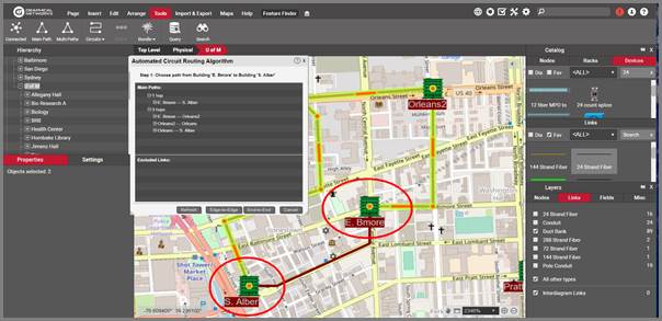
Two paths to get from point A to point Z
When discussing paths, consider the following concepts:
- Main path: this typically refers to the first path created for a circuit, usually the shortest route between the endpoints
- Secondary path: usually refers to a path created for a circuit that already has a main path, which is typically diverse or redundant
- Diverse path: a secondary path that has no common elements between the main path, except, of course, for the endpoints
- Redundant path: a secondary path that traverses the same hops on the map as the main path
8.9.2.1 Hops
In the picture above notice that the highlighted top path to get from building A. Alber to E. Bmore traverses through Orleans and Orleans2. These are intermediate hops. The top path has 3 hops to get from A to Z, the bottom path only 1, as it is a direct path.
In short, hops are the all the number of jumps on a map going from node to node, to make the trip from A to Z. When choosing an optimum path between A and Z netTerrain tries to minimize the number of hops.
In the following section we will review all the different ways of creating a circuit, now that we know the different types of paths that can comprise it.
8.9.3 Creating a new circuit
When creating a new circuit who decides which path it should take and how is that accomplished? There are basically three ways to define a path for a circuit, with decreasing levels of automation:
- By having netTerrain choose the shortest path
- By having netTerrain choose the shortest path and then modifying it
- By selecting the path on the map manually
Before we drill down into each method we should review some basic rules required for a circuit to even be created.
8.9.3.1 Rules for a valid circuit path to exist
Circuits require at least one path, so when you are looking for a valid path during the circuit creation process there are certain rules you need to abide by.
Rule 1:
A circuit is initially defined at the map level, so it requires two distinct endpoints on the map.
Rule 2:
You must have connectivity from A to Z at the map-level. A typical example of map-level connectivity for a fiber plant infrastructure is conduits connecting buildings and manholes.
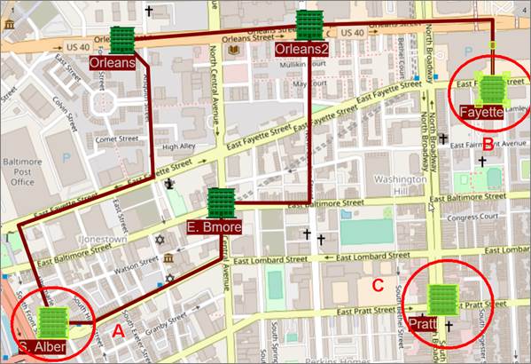
Valid map-level connectivity between A and B, but not between A and C.
Rule 3:
The map level connections (for instance, conduits) need to contain cables. In netTerrain parlance, a conduit containing a cable means that the cable is bundled to that conduit (please review the section on link bundling to learn how to do that). It’s important to note that you must have at least one level of bundling (such as cable to conduit), but you can have multiple bundling levels as well. For example, if your cable is bundled to a microduct bundled to a conduit bundled to a duct bank bundled to a trench, that is a legal configuration for ACRA to work. You can have unlimited bundling levels provided the cable eventually leads to the container map-level connection.
Rule 4:
Every cable along the path must have at least two available strands. An available strand is one that is connected to a port on both ends and is not already assigned to a circuit. We will review later what it means for a strand to be used by a circuit.
There is an additional addendum to these rules regarding the strands and it’s that a pair of strands used in a path need to terminate on ports that are on the same device.
Why all these rules, you may ask? Because that’s how most fiber plant environments are laid out: circuits go through strands, that are part of a fiber cable, that are bundled inside a cable container such as a microduct and so on, so netTerrain mimics real-life situations for a more intuitive and realistic user experience.
8.9.3.2 Step 1: Launching the ACRA
If you want to create an apple pie from scratch, first you must create the universe. And if you want to create a circuit from scratch, one that doesn’t even really exist in your environment, you use the ACRA.
Not the prettiest acronym in the world, ACRA stands for Automated Circuit Routing Algorithm dialog. ACRA is an algorithm that netTerrain uses to determine optimal routes between two points on a map following the four rules stated above. The algorithm is based on a method devised by Edsger Dijkstra's to find the shortest path between two nodes in a graph. No, Dijkstra is not a Graphical Networks employee.
To launch the ACRA utility, the endpoints are your basic known input parameters to start the circuit creation process:
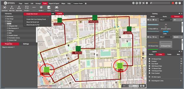
Creating a new circuit with two selected buildings
8.9.3.2.1 Choosing the paths
After clicking on the ‘Create new circuit’ option, a dialog for step 1 of the ACRA process pops up. There could be anywhere from zero paths available up to any number. The ACRA process will try to find two optimum paths: the shortest and a diverse secondary path. This may or may not be possible. If there are no routes available, netTerrain will let you know loud and clear, invoking the circuit rules mentioned earlier.
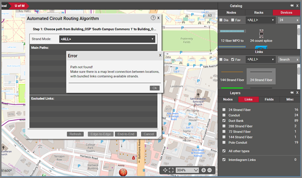
Path not found error
To recap, a path may not be found if:
- You are not choosing two distinct endpoints at the map level (in this case you won’t even be able to launch the dialog itself)
- No conduits connect the endpoints directly or through other nodes
- One or more conduits along the path have no bundled cables
- One or more bundled cables along the path have less than two available strands
If the two optimum paths (main and diverse) are found, they are displayed on the dialog.
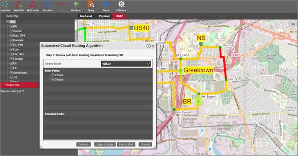
ACRA dialog showing two optimum paths (main and diverse)
You can click on any one of the paths shown and netTerrain will highlight them on the map, and expand it to how the hops, as shown below:
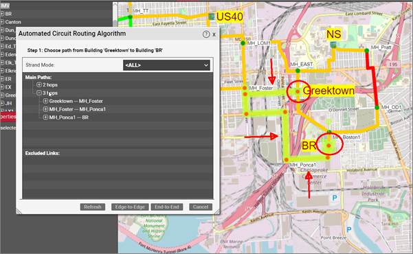
Secondary path highlighted with expanded hops
You can click on the other path and netTerrain will automatically zoom-in or out to make the entire path visible for you to review.
8.9.3.2.2 Selecting the cable mode
As part of the circuit design process sometimes you must make sure that all strands throughout the path are of the same mode. To prevent hybrid scenarios of single and multi-mode strands affecting the same circuit you can set the cable mode to any of the options available in the cable mode drop-down, as displayed below.
The mode of a specific cable type is defined in the catalog (see Power User guide), and the different mode options can be set in the settings.xml file (see Admin Guide).
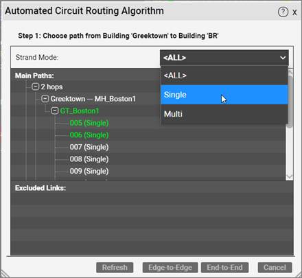
Selecting the cable mode
Once a mode is selected (other than All), then the ACRA process will limit all options (cables, hops, etc.) to ones that indeed use (or have) that mode.
8.9.3.2.3 Changing a hop
We mentioned that you can have netTerrain choose the shortest path and then modify it. This is done by excluding certain hops from the path and is useful in cases where you know a certain hop may be available in the system but should not be used for whatever reason.
To exclude a hop from the path right click on it and then click on the ‘Exclude’ option on the context menu:
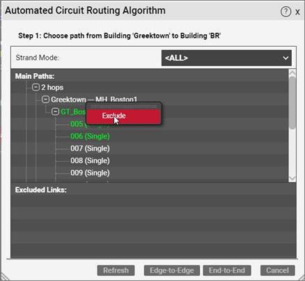
Excluding a hop from the path
Once the hop is excluded, it shows up in the ‘Excluded Links’ list and ACRA automatically refreshes the paths. To include the hop, you just right click on that hop in the Excluded Links list and include it again. It’s important to note that when a hop is excluded or included, it may not only affect the path that hop belongs to, but also the other path.
8.9.3.2.4 Changing the cables and strands
What about the cables and strands? How does netTerrain know which ones to use for each hop? It doesn’t, aside from the fact the cable must have available strands. netTerrain just selects the first cable and first pair of available strands based on name in ascending order. If you don’t like the cable that netTerrain chose for a hop and there are more, you can change the selection by expanding the hop and right-clicking on your preferred cable:
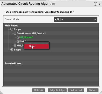
Selecting a different cable for a hop
The selected cable is displayed in green. You can also expand a cable and change the selected strands, one at a time. Remember that obscure additional rule for circuit creation, where a strand pair used for a path need to terminate on ports on the same equipment? Well, netTerrain does check that in this case. As a visual aid, any ports associated with a different device use a grey font.
This means that if you switch one strand to another that terminates on a different device, then netTerrain will automatically switch the other.
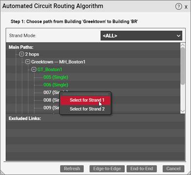
Changing the selected strands
Once you have your paths with the correct hops, cables and strands you go to step 2 of the circuit creation process picking one of two circuit types: edge-to-edge or end-to-end.
8.9.3.2.5 Selecting an ‘Intra-building’ cable (or inside connection)
In some cases, the cable that contains a strand section of your circuit path may flow between two floors, or two rooms in the same building or node at the map level.
Since ACRA in theory treats hops as nodes at the map level, how can a user specify a section of the path that is inside the same node? Enter the so-called inside connections.
To choose an inside connection for your path, you do it on a hop-by-hop basis. Right-click on the hop that needs an inside connection and click on the ‘Inside connection’ context menu.
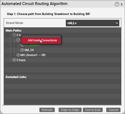
Choosing an inside connection for your circuit path
After clicking on the context menu create an inside connection by selecting entries from the ‘From’ and ‘To’ combo boxes. These contain all the sub nodes that exist in the Diagram specified on the top combo box, which is nothing more than the first node hop.
If no cables or nodes exist inside the map-level node, then one or both combo boxes will be empty.
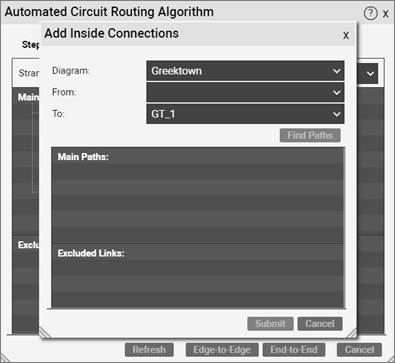
Adding an inside connection
Main paths and excluded links are selected in a similar fashion as with inter-building hops.
8.9.3.3 Step 2: Selecting the end devices
Since circuit paths utilize strands and patches (more on that later) to traverse the fiber network between points A and Z on the map, it is ultimately devices and a pair of ports on them that provide the physical infrastructure for a circuit path to exist.
In step 2 of the ACRA you get to choose those devices, unless you create a so-called edge-to-edge circuit, which we’ll review below.
8.9.3.3.1 Edge-to-edge versus end-to-end circuits
For the intermediate nodes, we sometimes refer to the “fiber equipment” as the hardware infrastructure that supports the paths. The purpose of the fiber equipment is to simply serve as transport for these circuits. This will become clear when we launch a circuit layout record.
We usually terminate the circuits in the A and Z locations on a network equipment, not on fiber equipment. After all, the circuit should serve an actual purpose for some network end user. In these cases, we refer to the circuit as “end-to-end”. More precisely, the circuit path is patched through fiber equipment in the intermediate nodes, and on the A and Z locations, there is an extra patch between the terminating fiber equipment (edge) and the final end-user or network equipment “end”. For end-to-end circuits, the user also must choose which network equipment the circuit should terminate on for both locations.
In some cases, however, you may not know which end equipment the circuit will serve. If you still want to create the circuit (perhaps to make sure nobody else takes up those resources), you can still do it by creating an “edge-to-edge” circuit. The next step in the ACRA process then is for you decide which circuit type you want.
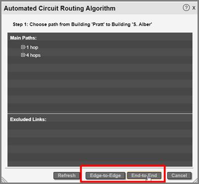
Selecting between an edge-to-edge and end-to-end circuit
8.9.3.3.2 Selecting an end-to-end circuit
If you choose an edge-to-edge circuit, netTerrain determines the endpoint fiber devices automatically. In that case there is no step 2 (well, the next step becomes step 2).
For an end-to-end circuit, netTerrain still selects the fiber devices on the A and Z locations, but you get to choose the end network equipment.
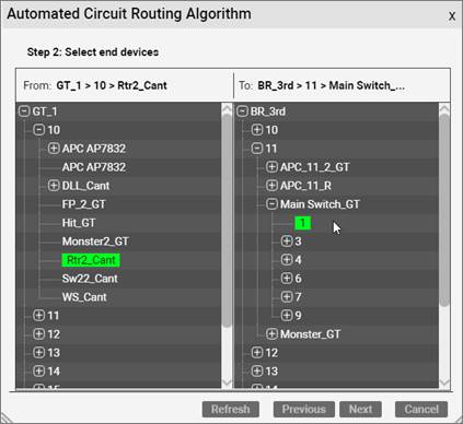
Selecting the end devices for an end-to-end circuit
Choosing the end devices is a simple process: in step 2 the ACRA shows you all the equipment (fiber or not) that exists in locations A and Z. They are displayed as a hierarchy browser on each side. The devices you pick are highlighted in green and all you need to do to confirm them is click on ‘Next’. If you are not sure about anything during the ACRA process you can always go to the previous step. There is also a refresh button to make sure you see the latest data. You know, in case you went for a long coffee break and you suspect somebody else may be lurking around creating circuits between the same end locations.
8.9.3.4 Final step: end ports, parameters and patching the circuit up
The final step of the ACRA consists of selecting the end ports of the devices picked for the A and Z locations, entering the parameters for the circuit and selecting the patch type.
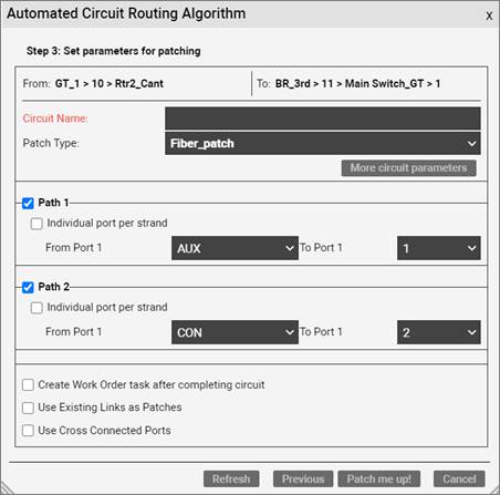
Step 3 of the ACRA process
Let’s start with the circuit name: this can be anything you want and is a mandatory field (hence the red color). Circuits can have any number of custom fields, so if you want to enter values for these custom properties, click on the ‘More circuit parameters’ button:
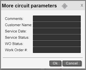
Adding additional property values for the circuit
For each intermediate node along each path, we have a device where the strands for the entering hop connect to, and a device where the strands for the departing hop exit. netTerrain will patches these up automatically for your circuit, so it has fiber continuity.
If you know you already have continuity and would like to use existing links as patches and existing cross connections, make sure you check the last two options in the dialog.
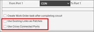
Using existing patches for the circuit creation
You can pick which type of patch netTerrain should use for this. This is done in the “Patch Type” field. This field is a drop-down box and it only shows types that have been enabled as valid for patching in the catalog (see Power-User Guide).
Each path can use individual ports per strands, or the default, which is two strands connecting to one port on the end equipment. Make sure to check the ‘Individual port per strand’ option if you want each strand to occupy an individual port on your end devices.
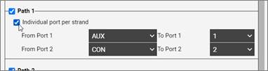
Using an individual port per strand
If you don’t want a secondary path for your circuit, you can uncheck it in this dialog. For any of these paths you can also choose the end ports they should terminate on the edge or end equipment.
As a final bonus, if you also want netTerrain to create a work order task for your circuit, make sure to check the ‘Create Work Order task after completing circuit’ checkbox.
Once you are done, click on the ‘Patch me up!’ button and this will complete the process. After some thinking, netTerrain will throw a message saying the circuit was created and prompt you to launch the CLR, which we will review later.
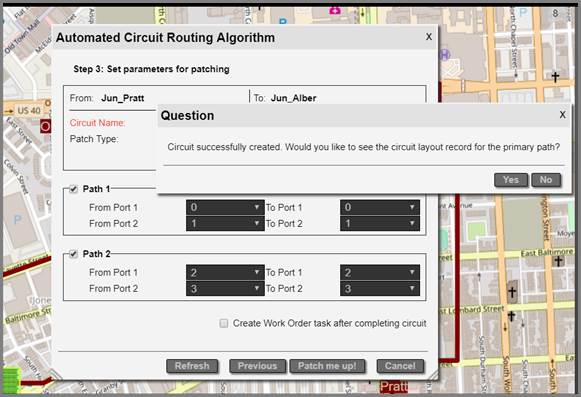
Circuit complete!
Interesting to note is that while this whole process seemed quite elaborate, it is still very automated: netTerrain picks the optimal paths for you, selects default cables and strands and even patches up the circuit along the way. Most of the explanations around this process deal with the details of how to override some of the decisions the software makes for you.
Being as automated as it is this process is prone to more automation through the API: you can have an external program send API calls to netTerrain via REST or SOAP and have the same circuit created 100% automatically without any human intervention.
8.9.3.5 Creating a circuit from a manual path selection
When you create a new circuit in netTerrain you may already know which path the circuit takes or maybe the circuit itself already exists in production. In that case you want to choose the path yourself and then “assign it to the circuit”.
This process is quite simple: select the conduits between the hops on the route and then click on the ‘Create New Circuit from Selected Path’ under Tools->Circuits:
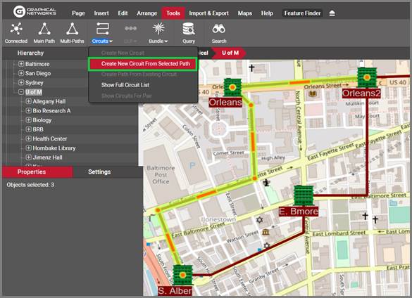
Creating a new circuit from an existing path
What follows next is the Automated Circuit Routing Algorithm dialog (or ACRA), which we already saw previously.
8.9.4 OSP circuit layout records
A circuit layout records (CLR) is an end-to-end view of a linear connection between two endpoints, in one page. We have seen these before, when we launched a CLR for a cable or a port: netTerrain tries to follow the path as far out as possible until it encounters no more connections or too many (a split).
With circuits however, we have a more granular definition of a CLR: a one-page view of one of the edge-to-edge or end-to-end paths a circuit takes. We even provide two flavors of that CLR: a block CLR and the traditional swimlane CLR.
8.9.4.1 Why a CLR?
Circuits in your fiber plant, as we have seen already, traverse from locations A to Z through intermediate nodes on a map. The underlying circuit infrastructure, however, is connected through strands and patches terminating on ports inside a card or device, mounted on a rack in a room, etc. As we can see there is a whole hierarchy of sub diagrams associated with each node. If we were to visualize the whole path of a circuit, we would have to start navigating netTerrain, clicking and double-clicking on objects and by the time we are done, we forgot where we started. Also, if you were to provide the information to a technician to configure the circuit in production, you would have to print a ton of diagrams and explain to that technician how netTerrain works. This is where the CLR comes in handy.
A CLR shows you all the information you need to know for the circuit, in one printable page without the need to navigate an array of different diagrams.
8.9.4.2 The block CLR
For both the block and the swimlane CLR views we show you each hop and each node, along with some properties. The difference between the two is in how we display these on the page. In the block CLR, each node down to the port is displayed as one simple block (hence the name).
Important to note is that a CLR shows you one path at a time.
Below is an example of a block CLR:
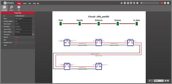
Block CLR for a secondary path
The block CLR shows two graphics: a top graphic representing the map-level path the circuit path takes and a bottom graphic showing the entire hierarchy for each node as text displayed next to the block representing that node hierarchy. It’s easy to see why a block CLR is convenient: by looping around the page, it can accommodate many hops.
Here is a detail of one of the nodes:
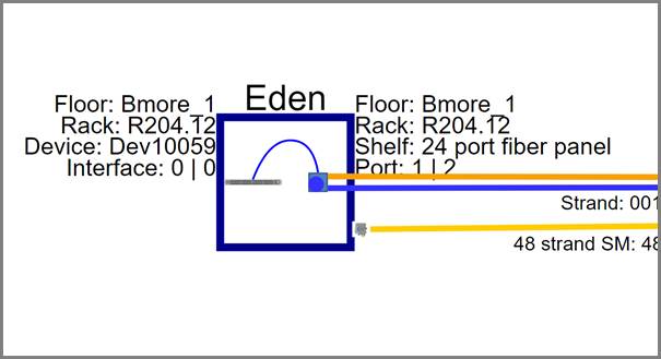
Node detail on the block CLR
The block includes a representation of the port where the strands and patches are connected and the cable that contains the strands. It also shows both port and strand numbers for each of the strands on the pair. For a pair of strands, two strands with their corresponding colors are shown.
The block CLR properties window shows the name and custom fields of the circuit, along with a link to see the main or secondary path (if it exists), a link to show you the circuit path on the map, and a link to open the swimlane view of the path:
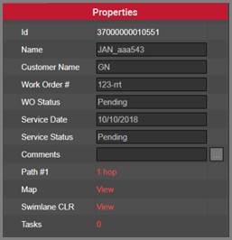
CLR properties window
8.9.4.3 Swimlane CLR
The swimlane CLR is somewhat similar except that it shows the entire hierarchy for each node and it does not loop around the diagram in the presence of many nodes, it just keeps drawing the path horizontally. This makes it less convenient for printing if the paths are long.
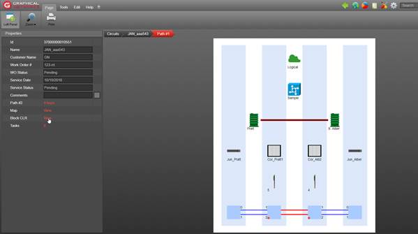
Swimlane CLR
From the swimlane CLR properties you can also access the alternate CLR paths, the map representation of the path and the block CLR view.
8.9.5 Diverse and redundant paths for existing circuits
Something quite important in fiber plant circuit design is ability to create redundant and diverse paths for an existing circuit.
We already saw in the circuit creation process above that when designing a new circuit netTerrain finds an optimal (shortest) path and the optimal diverse path. As we also saw above, a diverse path is a secondary, or alternative path that has no common elements with the main path, except, of course, for the endpoints. And we already know that a redundant path is a secondary path that traverses the same hops on the map as the main path.
Fiber circuits usually server as a transport mechanism for some service to internal or external end customers. The purpose of diverse and redundant circuits is to add some robustness to that service. Usually, diversity in a circuit gives us safeguards against physical damage to one of the paths. For example, a construction company may be digging on some street and cut a fiber cable. All the circuits that traverse that cable would be affected, but the ones without a diverse path would suffer a complete outage.
To view which circuits could be affected by such a fiber cut, you can click on the cable, or the conduit or any of the containers of circuits and get a list of the circuits going through that.
So, let’s suppose we have a circuit in netTerrain, and we would like to provide some robustness by creating a secondary route that is diverse. We start by selecting the circuit, which can be done directly from the map by choosing the end points for that circuit, then clicking on the circuits button->create path from existing circuit:
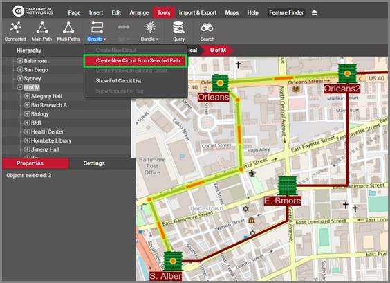
Creating a path from an existing circuit
This menu will bring up a report with all the circuits that exist between these two endpoints:
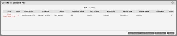
Circuit list for those two endpoints
From here you must select the circuit for which you want to create another diverse or redundant path (in the example above, it is the only one that exists) and either click on the ‘Add Diverse’ or ‘Add Redundant’ button. You are not guaranteed to have a path available, in which case netTerrain will show you an error. If there is a path, the ACRA dialog reviewed above is presented and you simply need to complete that same process.
8.9.6 Circuit Lists
To simplify the management of your circuits, netTerrain includes a variety of circuit lists that can be launched from different contexts.
8.9.6.1 Full circuit list
You can launch the full circuit list from the toolbar menu, as shown below:
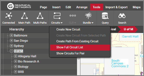
Full Circuit List menu item
There’s no mystery here: this button will open a list view with all the circuits that exist in your project. The list uses the well-known list view format we have already seen countless other times throughout the tool. A reduced list is the one that can be opened just for a pair of selected nodes by clicking on the menu below (Show Circuits For Pair). Important to note is that these lists provide a few convenient links and tools:
- Link to delete the circuit
- Link to view the circuit on the map
- Link to launch the CLR
- Link to launch a Bill of Materials (BOM)
- Link to show any Work order tasks
- Link to open a sublist of each path for that circuit
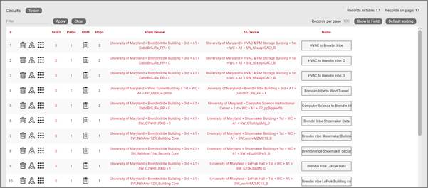
List view detail, showing shortcut links
8.9.6.1.1 Deleting a circuit
From the Delete button you can remove a circuit from the inventory permanently. Note that if you remove a circuit, you will also remove its paths and you will make any used strands available again. You will also be prompted to remove any existing patches currently used for that circuit.
8.9.6.1.2 Viewing circuit paths
Paths can also be viewed in simple list form. This is available on a per circuit basis by clicking on the Paths button available for each circuit:
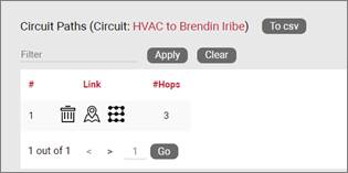
Circuit paths list
From this list you can also delete a path for a circuit, view it on the map or launch its CLR.
8.9.6.1.3 Launching a Bill of Materials (BOM)
A special type of report is the Bill of Materials (BOM), which you can launch by clicking on the BOM button available on the circuit list view. A BOM is a PDF report that is generated on the fly for the circuit showing a list of the patches that comprise it, along with a snippet of the affected map area (endpoints).
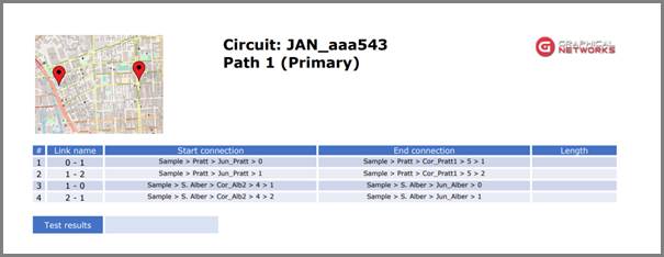
BOM report
8.9.6.2 Opening a list of affected circuits per node or link
You can click on any node, port or link and get a list of the circuits that go through that object. This is convenient way for launching a list of “affected circuits”. The usefulness of this feature is fairly obvious: if you need to relocate a building, or decommission a device, you can easily find out all the affected circuits by simply clicking on that object, as shown below:
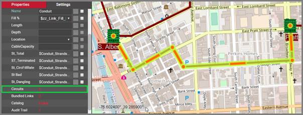
Link to access circuit list for a conduit
9 Dashboards
Dashboards (also called reports) are collections of gadgets showing aggregated data from the netTerrain database (customized dashboards may include data from other data sources).
The reports button opens a special reporting view, including several predefined dashboard views and reports.

Reports link
These gadgets present information in a number of different arrangements, such as:
- Charts
- Pies
- Gauges
- Cards
- Other gadgets (maps, pivots, grids, etc.)
9.1 Predefined dashboards
netTerrain ships with a series of default dashboards, which can later be overridden by changing the existing dashbaords or creating new ones using the netTerrain dashboard editor (see netTerrain Dashboard Designer Guide).
Attention!
Some of the default dashboards provided with netTerrain are geared towards DCIM-type data. If you are a user of netTerrain Logical, those dashboards may be hidden (see predefined dashboards below).
Dashboards can be designed so that only users with a certain permission level can view a specific dashboard. For example, the default dashboards include an administrator dashboard that can only be access by users with an admin role.
Users that access the dashboards will initially be presented with the default dashboard, which provides a summary of the project.
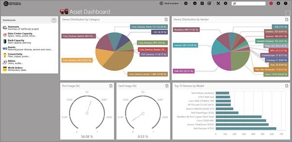
netTerrain summary (default) Dashboard
As mentioned above, netTerrain includes a series of predefined dashboards. In total, netTerrain ships with 6 dashboards, which are detailed below.
9.1.1 Summary dashboard
An example of the summary dashboard in netTerrain is shown above. This dashboard includes a basic summary of the components of the project including:
- A pie chart of the node counts and percentages by category, where the categories refer to the built-in categories such as nodes, devices, racks, etc (some of these categories may not be available for netTerrain Logical users).
- A pie chart of the node counts and percentages by type
-
A series of cards including scalar values (counts) for the following entities:
-
Diagrams (nodes containing other nodes)
- Nodes
- Cabinets
- Devices
- Links
- Cards
- Ports
- Palette Objects
9.1.2 Data Center Capacity (for netTerrain DCIM only)
The Data Center Capacity dashboard provides a summary of capacity statistics as well as four exception charts for rooms based on different criteria:
- A chart for the top 5 rooms by rack count
- A chart for the top 5 rooms by rack unit utilization [%]
- A chart for the top 5 rooms by rack weight utilization [%]
- A chart for the top 5 rooms by nameplate power utilization [%]
-
4 cards with the following capacity stats:
-
Room count
- Cabinet count
-
Rack unit (RU) usage (percentage), including:
-
Total rack units used
- The differential to reach the total RU capacity in the entire project
-
The percentage of RUs used
-
Power usage (percentage) in kW, including:
-
Total power used
- The differential to reach the total power capacity for the entire project
- The percentage of power used
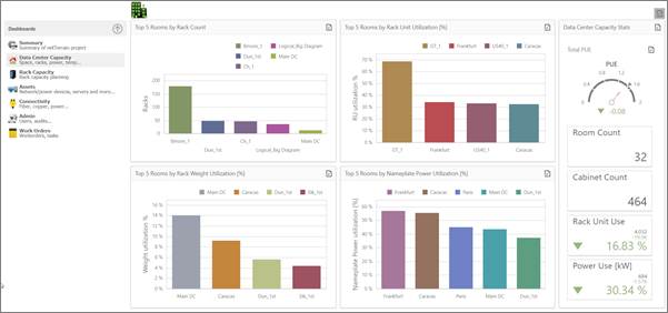
Data Center capacity planning dashboard
Attention!
A room is defined as any diagram (node) that contains at least one rack. Because netTerrain is so flexible, it lets users place racks at any level, so you may have ‘rooms’ that in the project appear at any level of depth.
Also notice that the power usage report here is based on nameplate power definitions for the devices in the netTerrain catalog. This is not instantaneous power and relies in the nameplate power figures being entered correctly in the catalog. Using the netTerrain environmental monitoring module users can obtain real-time, derated and other instantaneous power values.
9.1.3 Rack Capacity Planning Dashboard (for netTerrain DCIM only)
The Rack Capacity Planning dashboard provides a series of widgets depicting Rack Unit (RU), power and temperature aggregate data per room, including the following:
- Horizontal gauges depicting Rack RU capacity for each room
- Horizontal gauges depicting average rack temperature for each room
- Circular gauges depicting average rack nameplate power for each room
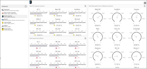
Rack capacity planning dashboard
Attention!
Rack power usage here is based on nameplate power definitions for the devices in the netTerrain catalog. This is not instantaneous power and relies in the nameplate power figures being entered correctly in the catalog. Using the netTerrain environmental monitoring module users can obtain real-time, derated and other instantaneous power values.
Temperature values are based on any values depicted in some field called ‘temperature’. This can be added manually, collected via SNMP or aggregated using our environmental monitoring module.
9.1.4 Asset Dashboard
The Asset dashboard provides a series of widgets depicting device distribution per category, per vendor as well as port and card usage percentages:
- Device distribution by vendor is shown as a pie chart assuming devices were placed in different categories (see Power User Guide)
- Device distribution by vendor also assumes devices in the catalog are associated with the correct vendor
- Port and card usages are represented in two circular gauges as percentage values
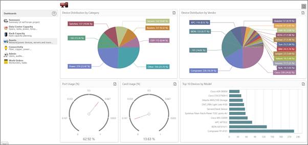
Asset dashboard
9.1.5 Connectivity Dashboard
The Connectivity dashboard provides a series of widgets depicting link counts by type, connectors and so, including:
- A full-stacked bar chart depicting endpoint counts by node and link type: for each different endpoint type in the project that has links (either as a starting point or an ending point) the corresponding bar shows the counts for each link type
- A pie chart showing the distribution of links by type
- A pie chart showing the distribution of cables by connector type (this only applies to DCIM)
- A pie chart showing the distribution of cables by type
Attention!
netTerrain does not discriminate between a link and a cable per-se, but cables in this context refer to any links that terminate on two ports.
9.1.6 Admin Dashboard
The Admin dashboard is, of course, only accessible for administrators and provides a series of widgets depicting user and audit trail related data, including:
- A pie chart of login counts, by user
- A pie chart of login attempts using bad credentials, by user
- A pie chart of distribution of users by role
- A stacked bar chart of audit trail events by action
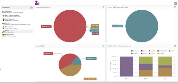
Admin dashboard
Attention!
This dashboard is only accessible by users with administrator credentials.
9.1.7 Work order Dashboard
The work order dashboard is only for administrators and provides a series of widgets depicting work order and task related data, including:
- A pie chart of tasks, by user
- A pie chart of tasks, by status
- A series of counters providing summarized task and work order information
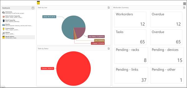
Work order dashboard
Attention!
This dashboard is only accessible by users with administrator credentials.
9.2 Dashboard drill down
Where applicable, dashboards allow drilling down from a specific widget into further levels of detail. To know which widget allows drilling down simply hover the mouse over it and when the mouse pointer shows the “hand” icon it means you can drill down into it.
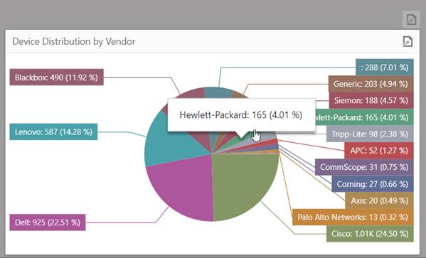
Dashboard allowing drill downs into a table view
For example, the devices by vendor widget that you can find in the assets dashboard (shown above) lets you drill down into a specific slice of the pie chart to open a table view of that particular slice. Since these tables are completely customizable as well, you can choose which columns to display in those table views.
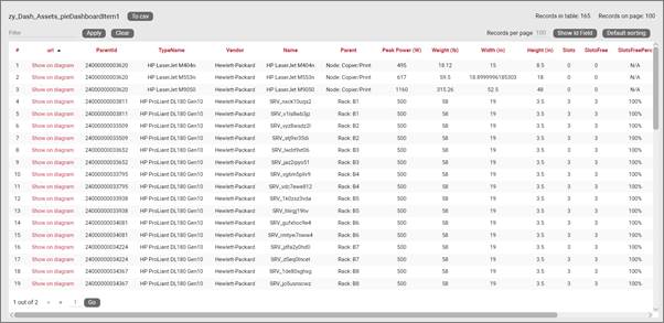
Table view for one of the slices of the dashboard shown above
10 Change management
netTerrain can be used as an advanced tool for change management. Two features stand out: document management and work order management, which we will explore in this chapter.
10.1 Document management (attachments)
netTerrain can be used to store documents and files, embedded with any node in the project. Users associate a document to a node by uploading the document from a local or network drive to the netTerrain server. When documents are uploaded to netTerrain, they reside in a netTerrain folder called ‘EmbeddedDocs’, which is on the application server.
The management of stored documents is akin to a SharePoint-Style document repository, and it includes features such as check-in, check-out, versioning, downloads, locking and history of files.
To manage documents, you must be a user with the annotator role or higher.
The ability to use netTerrain for document storage means that users can control the change and flow of documentation within the organization. Users can take advantage of this feature for the storage of user guides, processes, configuration files, diagrams designed with other tools, and much more.
10.1.1 Uploading a document
To upload a document first pick a node that will have these associated documents. You can associate as many documents as you want, and you can use as many nodes to embed documents as you want.
Start by right-clicking on the node and choosing the ‘Attachments’ menu, as depicted in the screenshot below. You can also click on the ‘Attachments’ button in the Insert menu.
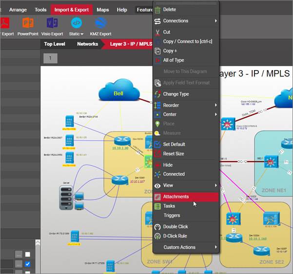
Accessing the document embedding feature for a node using attachments
After you click on the ‘attachments’ menu, a dialog box called ‘Embedded documents’ is displayed. A node without any embedded document initially looks like the dialog below. By clicking on the ‘Add new’ button, a dialog to upload a document is displayed.
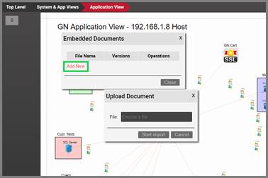
Document upload dialog
Click on the text box to browse for a document. If the document extension is valid (more on that later), then it can be uploaded by clicking on the ‘Start Upload’ button.
The uploaded document is then stored on the netTerrain server and displayed in the Embedded document dialog. As mentioned before, multiple documents can be embedded with a node, in which case the dialog looks as depicted below.
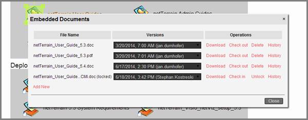
Embedded documents dialog
Embedded documents will be assigned a version and author, where the version is the date and time of the creation (or check in, see below) and the author is the user who originally uploaded it to the server.
Attention!
Uploaded documents must be unique across netTerrain. If you try to upload a document with the same name as another one associated with another node, netTerrain will display an error message and offer a link to show the containing node on the diagram.
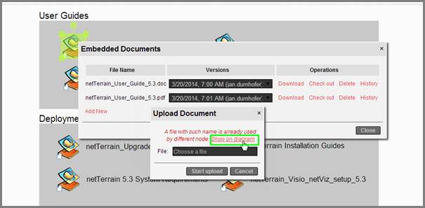
Repeated document name error
10.1.1.1 Deleting a document
To delete a document simply click on the delete button. This will remove the document from the netTerrain repository (although it still exists in the netTerrain folder).
10.1.2 Document extensions
In theory, any type of file can be uploaded to netTerrain, but administrators can control which extensions are accepted by listing them in the web.config file (see the netTerrain Installation guide).
If the extension of the selected document does not match any extension set up in the web.config file, then the following error will be displayed:
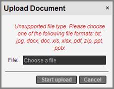
Unsupported file type error
10.1.3 Downloading, checking out and checking in documents
Let’s say we have a node with embedded documents, and a user wants to get a copy of a document. We have two options to do that: we can download it or check it out.
When we download a document from the server, we can store a copy of it on our local machine and work with as pleased, but that is pretty much all we can do with it. netTerrain will not allow a user to check a document back to the server when it was downloaded. What this means is that any changes the user makes to the document cannot be sent back to the server.
To store any new changes made to a document back to the server the user needs to do a ‘check out’ process. By checking out a document, the user in essence ‘locks it’ in netTerrain. After the document has been checked out, netTerrain remembers the user that has document locked and prevents any other user from checking it out. This user can then modify the document locally and check it back in.
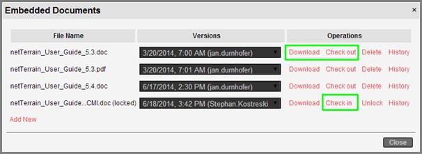
Download, check out and check in options
Naturally, many users can download a document and make changes locally, but only one user can check out a document at any given time. That way, we have in effect established a mechanism for document change control and prevent conflicting changes from occurring on the server.
To know who locked a document, hover the mouse over the locked document label, as depicted below.
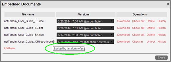
Locked document showing the user that is currently working with the checked-out document
Once the modified document is ready to be checked back in make sure it still has the same name as when it was checked out originally, otherwise an error occurs when attempting to check it in.
As soon as the document is checked back in, a new version is assigned to the checked in document, which is, as expected, determined by the date and time of the check in process.
All versions of the document are stored on the server and displayed in the corresponding drop-down box.
Attention!
Any version of the document can be downloaded, but only the latest can be checked out. That way we avoid any mistakes when editing the document and we ensure that we are always checking back in a version based on the latest changes.
10.1.4 Unlocking ‘dormant’ documents
There may be cases where a user checks out a document and then never checks it back in (or takes too long to do so). This could produce a bottleneck and prevent other users from making necessary modifications. In those cases, an administrator always has the power to ‘unlock’ the document. By unlocking a document, we are allowing other users to check it out. The administrator is bringing back the document to its previous state, and any changes that the ‘dormant’ user made will not be accepted.
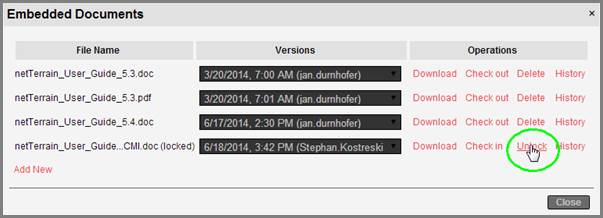
Unlocking a document
10.1.5 Document history
The entire sequence of events associated with a document is kept in an audit trail, which can be accessed by clicking on the ‘History’ button. This history is displayed in table views, like the audit trails available for nodes and links. In fact, the list view uses the same format as the audit trail list views.
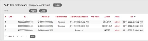
Document history
Attention!
When you delete a document, its history is also deleted as there is no user interface to access it any longer.
10.2 Work order management
Network configuration changes, data center installs, or outside plant resource commissioning are all activities that typically need some level of change control. Many organizations have dedicated software for the management of work orders and tasks associated with these activities.
netTerrain can integrate with third-party work order management (WOM) systems via the Integration Toolkit, APIs or some other method. However, organizations that either have no existing WOM system and need to start tracking work orders and tasks or have one but want to replace it, netTerrain also includes a module for that very purpose.
The advantage of the netTerrain WOM module over a standalone or separate WOM tool is that since it is part of the core netTerrain software it automatically reflects changes in tasks in the objects and diagrams visually represented in the system. In other words: no integration is needed!
The WOM module consists of two types of items: work orders and tasks, where a work order can have a collection of several tasks. Both work orders and tasks can be assigned to netTerrain users who get notified when a new item has been assigned to them.
10.2.1 Introduction to tasks
Tasks in the WOM module are essentially tags assigned to a netTerrain object. We will see that these are no ordinary tags, since there are several things you can do with tasks.
The objects in netTerrain that can have tasks assigned to them include:
- Any node
- Any link
- Racks
- Devices
- Cards
- Slots
- Line nodes
10.2.1.1 Categories of tasks
There are three main categories of tasks in a netTerrain WOM:
-
Add (or New) task
-
Delete task
-
‘Other’ task
Add tasks are probably the most important item in the netTerrain WOM, since they are used to mark an object as new. Generally, you want to create a new task for objects that are not in production, and when you use this type of task, as we will see, it triggers several useful features that ultimately lets the user visually see the planned network in a netTerrain project.
As we will see throughout this chapter, in some cases you can pick the category of task you are adding, but this is not always the case. Sometimes due to the context and business rules of the WOM you are prevented from creating certain categories of tasks.
10.2.2 Creating tasks
As mentioned before, tasks are associated to objects, so to create the task, you must first have an object to associate it too. At first, this may seem odd, especially if you have worked with other systems that use a different logic. You may wonder about two things:
a) What if the task I want to create is related to an object that does not exist?
This seems like a problem with netTerrain’s approach but it is one of its strengths: by first creating the object and then assigning the add task you are essentially creating a “planned” object. Later we will see how this can also be visualized properly.
b) What if the task is not related to any network object, why do I still have to create one?
Remember that the netTerrain catalog is extremely flexible, you could have a special object type in the catalog just devoted to general purpose tasks (or anything you imagine) and not have to rely on actual, physical objects to create your tasks, so this is not a problem
Once you have an object to assign the task to, simply right-click on it and select ‘Tasks’ (or alternatively click on the ‘Task’ button in the Insert menu).
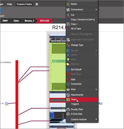
Work order task menu
If no tasks have been previously assigned to that object, an empty ‘Work Order Tasks’ lists prompts you to add a new task. Click on the ‘Add new’ link to create your new task.
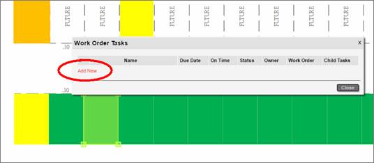
Creating a task
10.2.2.1 Default task name
When the ‘Add Work Order Task’ dialog pops up, a generic name for the task is displayed.
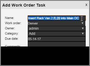
New task with default name
The task name is constructed as follows:
- The prefix ‘Insert’ is appended when the task category is ‘Add’
- The object type (in the example above, ‘Rack’) is appended next
- The object name (in the example above ‘Van.2.R.09) is appended next
- ‘into’ is appended for an Add task
- The parent name is added last
Of course, you can change the name of the task to anything you want.
10.2.2.2 Task work order
A task must have a parent work order. The second field in the ‘Add Work Order Task’ dialog lets you select an existing work order from the list of all existing work orders, or you can just type a new work order in the text box.
When you type a new work order in the text box it is created in the system, as soon as the task itself is created.
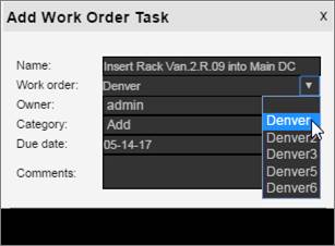
Choosing a parent work order for the task
10.2.2.3 Task owner
Next, you must choose an owner or stakeholder for the task. The owner is always a netTerrain user with editor rights or better. Updaters (or lower) cannot manage tasks, thus, they cannot be assigned any!
If the user doesn’t exist, it must be added first in the system (sorry, in that case you have to cancel the dialog and request the new user from the netTerrain sys admin).
When the task is created, the user will get a notification in the notification area that a task has been assigned to them (more on that later).
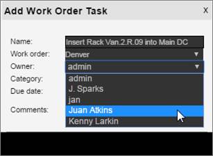
Choosing an owner for the task
10.2.2.4 Task category
As mentioned before, tasks come in three categories:
-
Add (or New) task: here you are essentially creating a “planned” object, which means that the object will be in production only after the task is closed. Later we will see how this can also be visualized properly, so that we identify objects that are still pending an add task as opposed to the ones already in production.
-
Delete task: this is the reverse of the add task, meaning that once the delete task is closed, then the associated object will be deleted as well.
-
‘Other’ task: this is a general-purpose bucket for tasks that are not adds or deletes.
When you create the first task for an object, if the object is a rack, device, node, link or card, then the default category is ‘Add’. You can pick any of the three categories, except for the object type slot, where the only available category is ‘Other’.
10.2.2.5 Task due date
Next you must pick a due date for the task. Note that later, after the task has been added, as soon as the task is due, the stakeholder will get a notification.
Also note that the date field is a calendar control that lets you choose a date in the past. This is ok, since sometimes tasks and work orders need to be recorded in the system, even if they have been completed already. Or maybe everybody was lazy, and the task simply might be due for real!
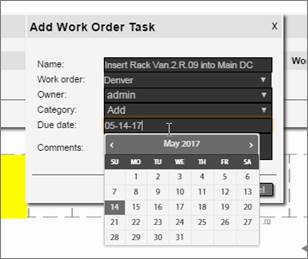
Choosing a due date for the task
10.2.2.6 Completing the task
The final field lets you add some comments for your work order task. Once you click ‘Submit’ the following actions are triggered:
- The task is added to a task list associated with its parent work order
- The stakeholder will get a notification for a new task added
- If the due date is already in the past, the stakeholder will get a notification as well
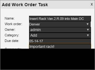
Completing the task
Upon submitting, the task list will now show our first task
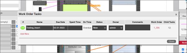
Work order task list for an object
Notice that if this was an ‘Add’ task, the ‘#’ column in our task list will have a green ‘Add’ icon. If the task is a delete task, the icon is red.
Also notice the extra columns that exist for the tasks:
- On Time - this column has two possible system generated values: On Time or Overdue.
- Status - an indicator of the status or stage of the task. We will review more of this later.
- Owner – person that owns the task
- Comments
- Work Order
- Child Tasks – this column indicates whether the object that has the task automatically created child tasks for objects that exist underneath. We will review more of this later in this chapter.
Attention!
Once you added a task, you cannot delete it from the task list. You have to go to the work order list and delete it from there.
10.2.2.7 Adding multiple tasks to the same object
You can add an unlimited number of tasks to an object, but take note of the following WOM rules:
- You can only have a maximum of one add task per object
- You can only have a maximum of one delete task per object
- You can not have an object containing both an add and a delete task
The task list orders tasks alphabetically and currently there is no mandatory sequence for completing the tasks on a work order or object.
Attention!
The list of tasks for an object are not correlated with a list of tasks for a work order (more on that later). An object can have tasks from multiple work orders and a work order can have tasks from multiple objects.
10.2.2.8 Copying tasks for links
You can copy a task from a link and then replicate that task throughout a selection of links. As we will see later, when you create an 'add task' for a device that already has links, netTerrain creates add tasks for underlying links in cascading fashion.
However, in some cases you may create a task for the device before any cables are created in netTerrain itself. That is one case where the copy feature comes in handy: it lets you quickly create tasks that you duplicate from an original task.
This feature is only available for links.
To copy and duplicate a link task do the following:
- Go to the task list for the link that contains the task you want to copy
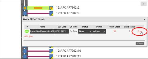
- Find the task you want to copy and click on the copy link
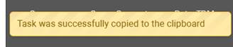
- Close the dialog and select the links for which you want to duplicate the copied task
- Open the context menu for the selected set and click on 'Tasks'
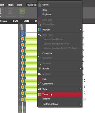
- Click 'Yes' on the dialog that pops up asking if you want to duplicate the copied task
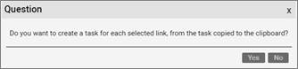
- The tasks are now pasted for each selected links
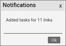
If the copied task was an add or delete task, any links that already had one such task type will be excluded from the process since you can only have one add or delete task for a given object.
10.2.3 Task status and stages
Currently tasks have several possible system-defined status values. The flow of status changes and how the owner is reassigned is up to the users of the WOM, but in general the flow goes from new to closed through several stages described below:
- New: this is the default status value a task has when created
- In Progress: this is an optional value to mark a task as being worked on by the stakeholder
- Completed: this is an optional value to mark a task as being completed by the stakeholder
- Approved: once a task is completed the stakeholder may reassign it to a task owner (or approver), who can mark it as approved.
- Rejected: a task previously marked as completed, may also be marked as rejected by the task owner (or approver).
- Closed: once the task is completed and approved it can be closed. We will go over the things that this status value triggers later in this chapter.
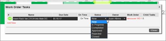
Task status values
A work order task that does not have the status value set to ‘closed’ is usually referred to as a pending task.
10.2.4 Editing a task
Once a task is created, it can later be edited. The fields that can be edited include:
- Name
- Due date
- Status
- Owner
You edit a task directly from a task list or from the work order task dialog, when clicking on the work order tasks menu:
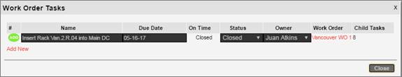
Editing a task
Attention!
The task category is not displayed in the work order task list because it cannot be edited after the task has been created.
10.2.5 Task visual overrides
One of the interesting features of the WOM is that objects with tasks can be viewed in netTerrain in such a way that they can be visually differentiated from the rest of the project. The main goal of this is to be able to see the network as planned versus the network as-is.
An object without a task is viewed in what may be called ‘normal’ mode. However, when an object has a task, we can differentiate it from the normal objects. Moreover, we can differentiate objects that have an add tasks and objects that have a delete tasks from the normal objects.
A netTerrain administrator can easily configure the system so that an object with an add task has a certain view mode and an object with a delete task has another.
These view modes make it easy for users to identify which objects may be pending an insert into production and which ones are about to be removed.
The possible visual overrides or view modes are the following:
- Outline mode: object only shows a grayish rectangle of the size of the rectangle that encompasses the normal icon. Links show a grey line.
- Normal mode: this mode shows the object just like normal ones without a task. in this mode we would not be able to distinguish objects with pending work order tasks
- Faint mode: object is displayed in a faint variant using the same icon as the object would have without a pending task
- Hidden mode: object is simply hidden
We typically recommend having the administrator set the viewing modes in such a way that we can differentiate objects with add tasks from objects with delete tasks and in turn, have those being displayed in a different way than normal objects. Below we show an example of racks with add and delete tasks:
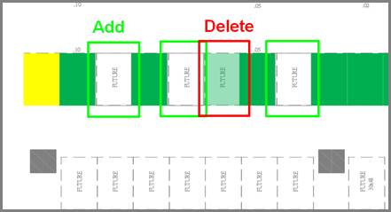
7 normal racks, 3 racks with pending add tasks and 1 rack with a pending delete task
10.2.6 Closing a task
As mentioned before, a task typically goes through several stages from the time it is created until it is closed. These stages may include changes in status from ‘new’ to ‘in progress’ to ‘completed’ to ‘approved’ or ‘rejected’ until it changes to its final status as ‘closed’.
When a task is closed, the object returns to normal mode in terms of its visual override. To close a task simply change its status to ‘Closed’.
10.2.7 Cascading task dependencies
An add task is the real-world equivalent of an object that does not exist in production yet. So, what happens to the objects underneath?
To preserve data consistency certain business rules apply when working with tasks across hierarchies in netTerrain. We review these next.
10.2.7.1 Creating an add task for a node with objects underneath
When you create an add task for a node with objects underneath, netTerrain will notify you of impending add tasks that will be added to all these (WOM applicable) objects that exist underneath. This is a necessity that derives from context: if the parent object is not in production yet, the dependent objects cannot be either. Don’t worry, netTerrain manages most of these business rules automatically.
For example, if I create an add task for a rack that has devices underneath, netTerrain will notify me of an impending cascading trigger: all devices will now have their corresponding add task added automatically.
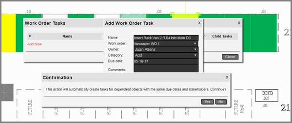
Cascading task creation for dependent objects
10.2.7.2 Closing a task with objects underneath
When I close a task for a node that has other objects underneath, then netTerrain will ask me if I want to close those related tasks too.
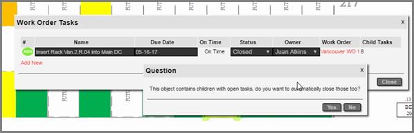
Automatically closing related tasks
Be careful though, you may have interdependent tasks that can prevent you from closing the tasks underneath altogether. For example, picture a rack that has pending tasks for devices underneath with pending tasks for cables that have endpoints to devices on a different rack that are also pending completion, closing all tasks from the original rack will not be possible.
The sure way to close all tasks without running into business rules contradictions is to work your way from the top down. So, for instance, first close the task for a rack, then for the device underneath and finally for the cables.
10.2.8 My work order tasks
As tasks are assigned to me, I can access them all from the ‘My work order tasks’ menu in the user menu:
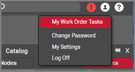
My work order tasks
When I click on the menu I get a list of all the tasks assigned to me:
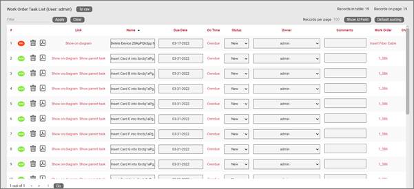
My work order tasks
From the list I can easily edit task, reassign them to other users, and change due dates and more.
This list also includes a link on the right to access the parent work order.
10.2.9 Task notifications
When a new task gets assigned to me or one of my tasks is past due, I get a notification in the top right notification section:

My notifications
The notification list first shows all my work orders and then all my tasks below.
From the notifications list I can click ‘Ok’ on a notification, which will mark it as read and make it disappear from the list or mark all of them as read.
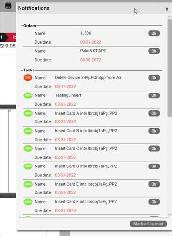
Notifications
10.2.10 Work orders
Work orders are the root WOM item, and mainly act as repositories of tasks. Work orders are not only useful to consolidate many tasks into one group, however. They can also serve to assign a responsible or stake holder to this collection of tasks and hence simplify the tracking of progress.
To create a work order you just create it from the task itself, as we saw in the example above when creating a task. Just type it in the work order text box upon creation of the task.
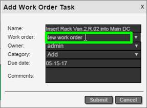
Creating a new work order by just typing it upon the task creation
10.2.10.1 Editing work orders
As an administrator you can manage and edit all work orders by clicking on the work order button on the quick access bar:

Accessing all work orders as an admin
If you are not an administrator, you can edit your work orders by accessing them from the ‘My work order tasks’ menu.
The work order list shows all the work orders along with editable text boxes for each, as well as some key links that let you access all tasks for a given order, all overdue tasks for a given order, all closed tasks, the user’s tasks, and the user’s overdue tasks:
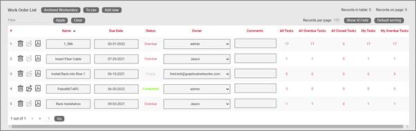
Work order list
The work order list, just like any list, can be sorted, filtered and exported to csv.
10.2.10.2 Archiving work orders
Work orders can be archived once all the dependent tasks have been closed. To archive a work order, go to the work order list and first make sure that the Status is marked in green as ‘completed’. You should also see the ‘Archive’ link enabled.
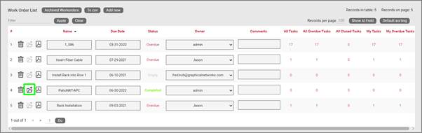
Archiving a work order
After you click on the ‘Archive’ link the work order will only be accessible from the archived list.
10.2.10.3 Viewing archived work orders
To view all the archived work orders, go to the work order list and then click on the ‘Archived Workorders’ button.
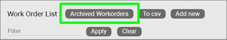
Accessing the archived work orders
Remember that to access the work order list you must be an admin.
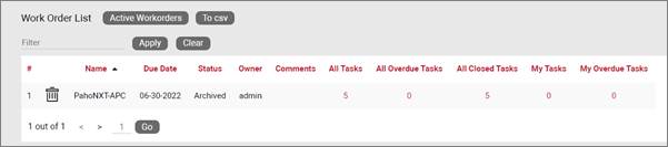
Archived work orders